Showing posts with label Electrical Bus. Show all posts

SUBSTATION ELECTRICAL BUS AND PARTS CLEARANCES REQUIREMENTS BASIC INFORMATION AND TUTORIALS


In 1972, the Substations Committee of the IEEE published Trans. Paper T72 131-6, which established recommendations for minimum line-to-ground electrical clearances for EHV substations based on switching-surge requirements. The recommendations are based on a study of actual test data of the switching-surge strength characteristics of air gaps with various electrode configurations as reported by many investigators.

The results are shown in Table 17-5 and include minimum line to- ground clearances for EHV system voltage ratings of 345, 500, and 765 kV.

The clearances given in Table 17-4 are considered adequate for both line-to-ground and phase-to-phase values for the voltage classes up through 230 kV nominal system voltage where air-gap distances are dictated by impulse (BIL) withstand characteristics.

The National Electric Safety Code, IEEE Standard C2-2002, also includes clearance requirements to the substation fence.

The Substations Committee of the IEEE has an ongoing effort to review phase-to-phase air clearances and is currently balloting IEEE Standard P1427, Guide for Recommended Electrical Clearances and Insulation Levels in Air Insulated Power Substations.

Considerable information has been published by CIGRE relative to establishing phase-to-phase air clearances in EHV substations as required by switching surges. The CIGRE method is based on nearly simultaneous and equal opposite-polarity surge overvoltages in adjacent phases.

The phase to-ground surge overvoltage is multiplied by a factor of up to 1.8 (the theoretical maximum phase to-phase voltage would be twice the phase-to-ground surge overvoltage). The estimated value of phase-to-phase overvoltage is then compared with obtained clearances. Refer to an article in CIGRE, Electra, no. 29, 1973, “Phase-to-Ground and Phase-to-Phase Air Clearances in Substations,” by L. Paris and A. Taschini.

Suggested values of phase-to-phase clearances for EHV substations based on the CIGRE method are shown in Table 17-6. The table was formulated by choosing various phase-to-ground transient voltage values such as are used in Table 17-5.

These values of phase-to-ground overvoltage were multiplied by a factor of 1.8 to arrive at a value of estimated phase-to-phase transient overvoltages.

An equivalent phase-to-phase critical flashover value of voltage is next assumed by multiplying the switching-surge phase-to-phase voltage by 1.21. Finally, this value is compared with data in the CIGRE article prepared by Paris and Taschini to arrive at air-clearance values based on switchingsurge impulse voltages.

EHV substation bus phase spacing is normally based on the clearance required for switching-surge impulse values plus an allowance for energized equipment projections and corona rings. This total distance may be further increased to facilitate substation maintenance.

TABLE 17-4 Minimum Electrical Clearances for Standard BIL Outdoor Alternating Current

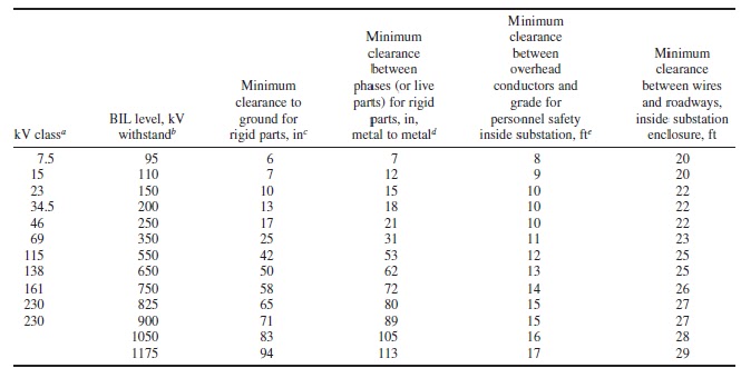
TABLE 17-5 Minimum Electrical Clearances for EHV Substations Based on Switching Surge and Lightning Impulse Requirements (Line to ground)

Notes:
1. Minimum clearances should satisfy either maximum switching-surge or BIL duty requirement, whichever dictates the larger dimension.
2. For installations at altitudes in excess of 3300 ft elevation, it is suggested that correction factors, as provided in IEEE C37.30-1992, be applied to withstand voltages as given above.

SS: switching surge
CFO: critical flashover
1 in # 25.4 mm.

TABLE 17-6 Suggested Electrical Clearances for EHV Substations Based on Switching Surge Requirements and Including U.S. Utility Practice (Phase to phase)
Note: 1 in # 25.4 mm; 1 ft # 0.3048 m.
∗The values of L-L switching-surge clearances are based on the use of SS L-G crest voltages multiplied by 1.8. This value of L-L SS voltage is then multiplied by 1.21 to indicate an SS CFO value of voltage used to determine the clearances.

For a description of method used, refer to CIGRE report by L. Paris and A. Taschini, Phase-to-Ground and Phase-to-Phase Air Clearances in Substations, CIGRE, Electra, no. 29, 1973, pp. 29–44. L-G: line to-ground; L-L: line-to-line; SS: switching surge; CFO: critical flashover.


RIGID AND STRAIN BUS COMPARISON FOR SUBSTATION USES BASIC INFORMATION


A comparison of rigid and strain buses indicates that careful consideration should be given to selection of the proper type of bus to use.

Rigid-bus advantages:
1. Less steel is used, and structures are of a simpler design.
2. Rigid conductors are not under constant strain.
3. Individual pedestal-mounted insulators are more accessible for cleaning.
4. The rigid bus is lower in height, has a distinct layout, and can be definitely segregated for maintenance.
5. Low profile with the rigid bus provides good visibility of the conductors and apparatus and gives a good appearance to the substation.

Rigid-bus disadvantages:
1. More insulators and supports are usually needed for rigid-bus design, thus requiring more insulators to clean.
2. The rigid bus is more sensitive to structural deflections, causing misalignment problems and
possible damage to the bus.
3. The rigid bus usually requires more land area than the strain bus.
4. Rigid-bus designs are comparatively expensive.

Strain-bus advantages:
1. Comparatively lower cost than the rigid bus.
2. Substations employing the strain bus may occupy less land area than stations using the rigid bus.
3. Fewer structures are required.

Strain-bus disadvantages:
1. Strain structures require larger structures and foundations.
2. Insulators are not conveniently accessible for cleaning.
3. Painting of high-steel structures is costly and hazardous.
4. Emergency conductor repairs are more difficult.

The design of station buses depends on a number of elements, which include the following:
1. Current-carrying capacity
2. Short-circuit stresses
3. Minimum electrical clearances

The current-carrying capacity of a bus is limited by the heating effects produced by the current. Buses generally are rated on the basis of the temperature rise, which can be permitted without danger of overheating equipment terminals, bus connections, and joints.

The permissible temperature rise for plain copper and aluminum buses is usually limited to 30°C above an ambient temperature of 40°C. This value is the accepted standard of IEEE, NEMA, and ANSI. This is an average temperature rise; a maximum or hot-spot temperature rise of 35°C is permissible.

Many factors enter into the heating of a bus, such as the type of material used, the size and shape of the conductor, the surface area of the conductor and its condition, skin effect, proximity effect, conductor reactance, ventilation, and inductive heating caused by the proximity of magnetic materials.

ADVANTAGES AND DISADVANTAGES OF DIFFERENT SUBSTATION SCHEMES COMPARISON OF CONFIGURATIONS


Below is a summary of comparison of switching schemes for substations.

A. SINGLE BUS SCHEME
Advantages
1. Lowest cost.

Disadvantages
1. Failure of bus or any circuit breaker results in shutdown of entire substation.
2. Difficult to do any maintenance.
3. Bus cannot be extended without completely deenergizing substation.
4. Can be used only where loads can be interrupted or have other supply arrangements.

B. DOUBLE BUS DOUBLE BREAKER SCHEME
Advantages
1. Each circuit has two dedicated breakers.
2. Has flexibility in permitting feeder circuits to be connected to either bus.
3. Any breaker can be taken out of service for maintenance.
4. High reliability.

Disadvantages
1. Most expensive.
2. Would lose half of the circuits for breaker failure if circuits are not connected to both buses.

C. MAIN AND TRANSFER BUS SCHEME
Advantages
1. Low initial and ultimate cost.
2. Any breaker can be taken out of service for maintenance.
3. Potential devices may be used on the main bus for relaying.

Disadvantages
1. Requires one extra breaker for the bus tie.
2. Switching is somewhat complicated when maintaining a breaker.
3. Failure of bus or any circuit breaker results in shutdown of entire substation.

D. DOUBLE BUS, SINGLE BREAKER SCHEME
Advantages
1. Permits some flexibility with two operating buses.
2. Either main bus may be isolated for maintenance.
3. Circuit can be transferred readily from one bus to the other by use of bus-tie breaker and bus selector disconnect switches.

Disadvantages
1. One extra breaker is required for the bus tie.
2. Four switches are required per circuit.
3. Bus protection scheme may cause loss of substation when it operates if all circuits are connected to that bus.
4. High exposure to bus faults.
5. Line breaker failure takes all circuits connected to that bus out of service.
6. Bus-tie breaker failure takes entire substation out of service.

E. RING BUS SCHEME
Advantages
1. Low initial and ultimate cost.
2. Flexible operation for breaker maintenance.
3. Any breaker can be removed for maintenance without interrupting load.
4. Requires only one breaker per circuit.
5. Does not use main bus.
6. Each circuit is fed by two breakers.
7. All switching is done with breakers.

Disadvantages
1. If a fault occurs during a breaker maintenance period, the ring can be separated into two sections.
2. Automatic reclosing and protective relaying circuitry rather complex.
3. If a single set of relays is used, the circuit must be taken out of service to maintain the relays. (Common on all schemes.)
4. Requires potential devices on all circuits since there is no definite potential reference point. These devices may be required in all cases for synchronizing, live line, or voltage indication.
5. Breaker failure during a fault on one of the circuits causes loss of one additional circuit owing to operation of breaker-failure relaying.

F. BREAKER AND A HALF SCHEME
Advantages
1. Most flexible operation.
2. High reliability.
3. Breaker failure of bus side breakers removes only one circuit from service.
4. All switching is done with breakers.
5. Simple operation; no disconnect switching required for normal operation.
6. Either main bus can be taken out of service at any time for maintenance.
7. Bus failure does not remove any feeder circuits from service.

Disadvantages
1. 1 1/2 breakers per circuit.
2. Relaying and automatic reclosing are somewhat involved since the middle breaker must be responsive to either of its associated circuits.

BREAKER AND A HALF SUBSTATION SCHEME – BASIC INFORMATION AND TUTORIALS


The breaker-and-a-half scheme can be developed from a ring bus arrangement as the number of circuits increases. In this scheme, each circuit is between two circuit breakers, and there are two main buses.

The breaker-and-a half scheme, sometimes called the three-switch scheme, has three breakers in series between two main buses. Two circuits are connected between the three breakers, hence the term breaker and a half. This pattern is repeated along the main buses so that one and a half breakers are used for each circuit.

Under normal operating conditions, all breakers are closed, and both buses are energized. A circuit is tripped by opening the two associated circuit breakers. Tiebreaker failure will trip one additional circuit, but no additional circuit is lost if a line trip involves failure of a bus breaker.

  
Either bus may be taken out of service at any time with no loss of service. With sources connected opposite to loads, it is possible to operate with both buses out of service. Breaker maintenance can be done with no loss of service, no relay changes, and simple operation of the breaker disconnects.

The failure of a circuit will trip the two adjacent breakers and not interrupt any other circuit. With the three breaker arrangement for each bay, a center breaker failure will cause the loss of the two adjacent circuits.

However, a breaker failure of the breaker adjacent to the bus will only interrupt one circuit. Maintenance of a breaker on this scheme can be performed without an outage to any circuit.

Furthermore, either bus can be taken out of service with no interruption to the service. This is one of the most reliable arrangements, and it can continue to be expanded as required. Relaying is more involved than some schemes previously discussed. This scheme will require more area and is costly due to the additional components.

The breaker-and-a-half arrangement is more expensive than the other schemes, with the exception of the double breaker, double-bus scheme, and protective relaying and automatic reclosing schemes are more complex than for other schemes. However, the breaker-and-a half scheme is superior in flexibility, reliability, and safety.

RING BUS SUBSTATION SCHEME – BASIC INFORMATION AND TUTORIALS


In this scheme, as indicated by the name, all breakers are arranged in a ring with circuits tapped between breakers. For a failure on a circuit, the two adjacent breakers will trip without affecting the rest of the system.  


In the ring-bus scheme, the breakers are arranged in a ring with circuits connected between breakers. There are the same number of circuits as there are breakers.

During normal operation, all breakers are closed. For a circuit fault, two breakers are tripped, and in the event that one of the breakers fails to operate to clear the fault, an additional circuit will be tripped by operation of breaker-failure backup relays. During breaker maintenance, the ring is broken, but all lines remain in service.

Similarly, a single bus failure will only affect the adjacent breakers and allow the rest of the system to remain energized. However, a breaker failure or breakers that fail to trip will require adjacent breakers to be tripped to isolate the fault.

Maintenance on a circuit breaker in this scheme can be accomplished without interrupting any circuit, including the two circuits adjacent to the breaker being maintained. The breaker to be maintained is taken out of service by tripping the breaker, then opening its isolation switches.

Since the other breakers adjacent to the breaker being maintained are in service, they will continue to supply the circuits.

The circuits connected to the ring are arranged so that sources are alternated with loads. For an extended circuit outage, the line-disconnect switch may be opened, and the ring can be closed. No changes to protective relays are required for any of the various operating conditions or during maintenance.

In order to gain the highest reliability with a ring bus scheme, load and source circuits should be alternated when connecting to the scheme. Arranging the scheme in this manner will minimize the potential for the loss of the supply to the ring bus due to a breaker failure.

Relaying is more complex in this scheme than some previously identified. Since there is only one bus in this scheme, the area required to develop this scheme is less than some of the previously discussed schemes. However, expansion of a ring bus is limited, due to the practical arrangement of circuits.

The ring-bus scheme is relatively economical in cost, has good reliability, is flexible, and is normally considered suitable for important substations up to a limit of five circuits. Protective relaying and automatic reclosing are more complex than for previously described schemes.

It is common practice to build major substations initially as a ring bus; for more than five outgoing circuits, the ring bus is usually converted to the breaker-and-a-half scheme.  

DOUBLE BUS DOUBLE-BREAKER SUBSTATION SCHEME – BASIC INFORMATION AND TUTORIALS


Double Bus, Double Breaker.

The double bus, double breaker scheme requires two circuit breakers for each feeder circuit. Normally, each circuit is connected to both buses. In some cases, half the circuits operate on each bus.

This scheme provides a very high level of reliability by having two separate breakers available to each circuit. In addition, with two separate buses, failure of a single bus will not impact either line.

For these cases, a bus or breaker failure would cause loss of only half the circuits, which could be rapidly corrected through switching. The physical location of the two main buses must be selected in relation to each other to minimize the possibility of faults spreading to both buses.

The use of two breakers per circuit makes this scheme expensive; however, it does represent a high degree of reliability.

Maintenance of a bus or a circuit breaker in this arrangement can be accomplished without interrupting either of the circuits.

This arrangement allows various operating options as additional lines are added to the arrangement; loading on the system can be shifted by connecting lines to only one bus.

A double bus, double breaker scheme is a high-cost arrangement, since each line has two breakers and requires a larger area for the substation to accommodate the additional equipment. This is especially true in a low profile configuration.

The protection scheme is also more involved than a single bus scheme.

Below is the diagram of a double bus double breaker substation scheme:


DOUBLE BUS SINGLE-BREAKER SUBSTATION SCHEME – BASIC INFORMATION AND TUTORIALS


This scheme uses two main buses, and each circuit includes two bus selector disconnect switches. A bus-tie circuit connects to the two main buses and, when closed, allows transfer of a feeder from one bus to the other bus without deenergizing the feeder circuit by operating the bus selector disconnect switches.  


This arrangement allows the operation of the circuits from either bus. In this arrangement, a failure on one bus will not affect the other bus. However, a bus tie breaker failure will cause the outage of the entire system.

The circuits may all operate from either the no. 1 or no. 2 main bus, or half the circuits may be operated off either bus. In the first case, the station will be out of service for bus or breaker failure. In the second case, half the circuits will be lost for bus or breaker failure.

Operating the bus tie breaker in the normally open position defeats the advantages of the two main buses. It arranges the system into two single bus systems, which as described previously, has very low reliability.

Relay protection for this scheme can be complex, depending on the system requirements, flexibility, and needs. With two buses and a bus tie available, there is some ease in doing maintenance, but maintenance on line breakers and switches would still require outside the substation switching to avoid outages.

In some cases circuits operate from both the no. 1 and no. 2 bus, and the bus-tie breaker is normally operated closed. For this type of operation, a very selective bus-protective relaying scheme is required to prevent complete loss of the station for a fault on either bus.

Disconnect-switch operation becomes quite involved, with the possibility of operator error, injury, and possible outage. The double-bus, single-breaker scheme is relatively poor in reliability and is not normally used for important substations.

MAIN AND TRANSFER BUS SUBSTATION SCHEME – BASIC INFORMATION AND TUTORIALS


The main- and transfer-bus scheme adds a transfer bus to the single-bus scheme. An extra bus-tie circuit breaker is provided to tie the main and transfer buses together.

This scheme is arranged with all circuits connected between a main (operating) bus and a transfer bus (also referred to as an inspection bus). Some arrangements include a bus tie breaker that is connected between both buses with no circuits connected to it.

Since all circuits are connected to the single, main bus, reliability of this system is not very high. However, with the transfer bus available during maintenance, de-energizing of the circuit can be avoided. Some systems are operated with the transfer bus normally de-energized.

When a circuit breaker is removed from service for maintenance, the bus-tie circuit breaker is used to keep that circuit energized. Unless the protective relays are also transferred, the bus-tie relaying must be capable of protecting transmission lines or generation sources. This is considered rather unsatisfactory because relaying selectivity is poor.

A satisfactory alternative consists of connecting the line and bus relaying to current transformers located on the lines rather than on the breakers. For this arrangement, line and bus relaying need not be transferred when a circuit breaker is taken out of service for maintenance, with the bus-tie breaker used to keep the circuit energized.


When maintenance work is necessary, the transfer bus is energized by either closing the tie breaker, or when a tie breaker is not installed, closing the switches connected to the transfer bus. With these switches closed, the breaker to be maintained can be opened along with its isolation switches.

Then the breaker is taken out of service. The circuit breaker remaining in service will now be connected to both circuits through the transfer bus. This way, both circuits remain energized during maintenance.

Since each circuit may have a different circuit configuration, special relay settings may be used when operating in this abnormal arrangement. When a bus tie breaker is present, the bus tie breaker is the breaker used to replace the breaker being maintained, and the other breaker is not connected to the transfer bus.

A shortcoming of this scheme is that if the main bus is taken out of service, even though the circuits can remain energized through the transfer bus and its associated switches, there would be no relay protection for the circuits. Depending on the system arrangement, this concern can be minimized through the use of circuit protection devices (reclosure or fuses) on the lines outside the substation.

If the main bus is ever taken out of service for maintenance, no circuit breakers remain to protect
any of the feeder circuits. Failure of any breaker or failure of the main bus can cause complete loss
of service of the station.

Due to its relative complexity, disconnect-switch operation with the main- and transfer-bus
scheme can lead to operator error and a possible outage. Although this scheme is low in cost and
enjoys some popularity, it may not provide as high a degree of reliability and flexibility as required.

This arrangement is slightly more expensive than the single bus arrangement, but does provide more flexibility during maintenance. Protection of this scheme is similar to that of the single bus arrangement. The area required for a low profile substation with a main and transfer bus scheme is also greater than that of the single bus, due to the additional switches and bus.

SINGLE BUS SUBSTATION SCHEME – BASIC INFORMATION AND TUTORIALS


Single Bus Scheme In Substation
The single-bus scheme is not normally used for major substations. Dependence on one main bus can cause a serious outage in the event of breaker or bus failure without the use of mobile equipment.

  
This arrangement involves one main bus with all circuits connected directly to the bus. The reliability of this type of an arrangement is very low. When properly protected by relaying, a single failure to the main bus or any circuit section between its circuit breaker and the main bus will cause an outage of the
entire system.

In addition, maintenance of devices on this system requires the de-energizing of the line connected to the device. Maintenance of the bus would require the outage of the total system, use of standby generation, or switching to adjacent station, if available.

The station must be deenergized in order to carry out bus maintenance or add bus extensions. Although the protective relaying is relatively simple for this scheme, the single-bus scheme is considered inflexible and subject to complete outages of extended duration.

Since the single bus arrangement is low in reliability, it is not recommended for heavily loaded substations or substations having a high availability requirement. Reliability of this arrangement can be improved by the addition of a bus tiebreaker to minimize the effect of a main bus failure.

GENERATOR CLOSING UNTO DEAD BUS BASIC TUTORIALS


Closing onto a Dead Bus with Leading PF Load
It is possible to have a power system configuration where a bus might have capacitive loading.
• Static capacitors connected to it.
• Energizing a long high voltage transmission line. Note HV lines inherently appear like capacitors, which are able to supply MVARs.

In the capacitive loading situations the generator would have to absorb these MVARs. If the Automatic Voltage Regulator is in the Auto mode, the generator excitation is automatically decreased to cause the generator to take in the required MVARs and to hold the terminal voltage.

If the Automatic Voltage Regulator is in the manual mode, the excitation is constant and the leading power factor current which is required for the generator to take in MVARs could cause the generator terminal voltage to go very high.

Closing onto a Dead Bus with Lagging PF Load
Inductive loading can take the form of:
• Connected power transformers
• Motor Loads

Inductive loading will cause a significant voltage drop when the generator breaker is closed, due to the load absorbing MVARS.

Closing onto a Faulted Bus
Closing the generator output breakers onto a bus, which has a short circuit fault, can cause generator damage because of high winding currents, stresses and possible pole slipping.

Closing onto a Dead Bus with no Connected Loads
This should not present a problem as long as the bus has been proven to be free of faults or working grounds.

GENERATOR LOADING
Closing onto a Finite vs Infinite System
When we enter into the topic of generator loading we must consider whether or not the connected electrical system is very large and hence strong or smaller and weaker. The first is classed as infinite and the second finite.

A generator connected to a very large (infinite bus) electrical system will have little or no effect on its voltage or frequency. In contrast, a generator connected to a finite bus does have a substantial effect on voltage and frequency.

It is normally assumed that when a generator has a capacity of greater than 5% of the system size, then with respect to this generator, the system does not behave as an infinite bus. For example, when an 800 MW generator is loaded onto a grid having a capacity of l0,000 MW, the system voltage and frequency can vary and the system will behave
free counters