Showing posts with label Synchronous Machines. Show all posts

BRUSHLESS SERVOMOTORS BASIC INFORMATION


A synchronous machine with permanent magnets on the rotor is the heart of the modern brushless servomotor drive. The motor stays in synchronism with the frequency of supply, though there is a limit to the maximum torque which can be developed before the rotor is forced out of synchronism, pull-out torque being typically between 1.5 and 4 times the continuously rated torque.

The torque–speed curve is therefore simply a vertical line. The industrial application of brushless servomotors has grown significantly for the following reasons:

● reduction of price of power conversion products
● establishment of advanced control of PWM inverters
● development of new, more powerful and easier to use permanent magnet materials
● the developing need for highly accurate position control
● the manufacture of all these components in a very compact form

They are, in principle, easy to control because the torque is generated in proportion to the current. In addition, they have high efficiency, and high dynamic responses can be achieved.

Brushless servomotors are often called brushless dc servomotors because their structure is different from that of dc servomotors. They rectify current by means of transistor switching within the associated drive or amplifier, instead of a commutator as used in dc servomotors.

Confusingly, they are also called ac servomotors because brushless servomotors of the synchronous type (with a permanent magnet rotor) detect the position of the rotational magnetic field to control the three-phase current of the armature. It is now widely recognized that brushless ac refers to a motor with a sinusoidal stator winding distribution which is designed for use on a sinusoidal or PWM inverter supply voltage.

Brushless dc refers to a motor with a trapezoidal stator winding distribution which is designed for use on a square wave or block commutation inverter supply voltage.

The brushless servomotor lacks the commutator of the dc motor, and has a device (the drive, sometimes referred to as the amplifier) for making the current flow according to the rotor position. In the dc motor, increasing the number of commutator segments reduces torque variation.

In the brushless motor, torque variation is reduced by making the coil three-phase and, in the steady state, by controlling the current of each phase into a sine wave.

SHAFT CURRENT, BEARING INSULATION, AND PHASE SEQUENCE TEST OF SYNCHRONOUS GENERATORS


Shaft Current and Bearing Insulation
Irregularities in the SG magnetic circuit lead to a small axial flux that links the shaft. A parasitic current occurs in the shaft, bearings, and machine frame, unless the bearings are insulated from stator core or from rotor shaft.

The presence of pulse-width modulator (PWM) static converters in the stator (or rotor) of SG augments this phenomenon. The pertinent testing is performed with the machine at no load and rated voltage. The voltage between shaft ends is measured with a high impedance voltmeter.

The same current flows through the bearing radially to the stator frame. The presence of voltage across bearing oil film (in uninsulated bearings) is also an indication of the shaft voltage.

If insulated bearings are used, their effectiveness is checked by shorting the insulation and observing an increased shaft voltage. Shaft voltage above a few volts, with insulated bearings, is considered unacceptable due to bearing in-time damage.

Generally, grounded brushes in shaft ends are necessary to prevent it.

Phase Sequence
Phase sequencing is required for securing given rotation direction or for correct phasing of a generator prepared for power bus connection. As known, phase sequencing can be reversed by interchanging any two armature (stator) terminals.

There are a few procedures used to check phase sequence:

• With a phase-sequence indicator (or induction machine)
• With a neon-lamp phase-sequence indicator (Figure 8.1a and Figure 8.1b)
• With the lamp method (Figure 8.1b)

When the SG no-load voltage sequence is 1–2–3 (clockwise), the neon lamp 1 will glow, while for the 1–3–2 sequence, the neon lamp 2 will glow. The test switch is open during these checks.

The apparatus works correctly if, when the test switch is closed, both lamps glow with the same intensity (Figure 8.1a).

FIGURE 8.1 Phase-sequence indicators: (a) independent (1–2–3 or 1–3–2) and (b) relative to power grid.

With four voltage transformers and four lamps (Figure 8.1b), the relative sequence of SG phases to power grid is checked. For direct voltage sequence, all four lamps brighten and dim simultaneously. For the opposite sequence, the two groups of lamps brighten and dim one after the other.


TESTS FOR SHORT-CIRCUITED FIELD TURNS AND POLARITY TEST FOR FIELD INSULATION OF SYNCHRONOUS GENERATORS


The purpose of these tests is to check for field-coil short-circuited turns, for number of turns/coil, or for short-circuit conductor size. Besides tests at standstill, a test at rated speed is required, as short circuited turns may occur at various speeds.

There are DC and alternating current (AC) voltage tests for the scope. The DC or AC voltage drop across each field coil is measured.

A more than +2% difference between the coil voltage drop indicates possible short-circuits in the respective coils. The method is adequate for salient-pole rotors.

For cylindrical rotors, the DC field-winding resistance is measured and compared with values from previous tests. A smaller resistance indicates that short-circuited turns may be present.

Also, a short-circuited coil with a U-shaped core may be placed to bridge one coil slot. The U-shaped core coil is placed successively on all rotor slots.

The field-winding voltage or the impedance of the winding voltage or the impedance of the exciting coil decreases in case there are some short-circuited turns in the respective field coil.

Alternatively, a Hall flux probe may be moved in the airgap from pole to pole and measures the flux density value and polarity at standstill, with the field coil DC fed at 5 to 10% of rated current value.

If the flux density amplitude is higher or smaller than that for the neighboring poles, some field coil turns are short-circuited (or the airgap is larger) for the corresponding rotor pole.

If the flux density does not switch polarity regularly (after each pole), the field coil connections are not correct.

SELF-STARTING SYNCHRONOUS-RELUCTANCE MOTORS BASIC INFORMATION


Any one of the induction-motor types described above can be made into a self-starting synchronous reluctance motor.

Anything which makes the reluctance of the air gap a function of the angular position of the rotor with respect to the stator coil axis will produce reluctance torque when the rotor is revolving at synchronous speed.

For example, suppose some of the teeth are removed from a squirrel-cage rotor, leaving the bars and end tings intact, as in an ordinary squirrel-cage induction motor. Figure 9.9a shows a lamination for such a rotor designed for use with a four-pole stator.

The stator may be polyphase or any one of the single-phase types described above. The motor will start as an induction motor and at light loads will speed up to a small value of slip.

The reluctance torque arises from the tendency of the rotor to try to align itself in the minimum reluctance position with respect to the synchronously revolving forward air-gap flux wave.

At a small slip, this torque alternates slowly in direction; the rotor is accelerated during a positive half cycle of the torque variation and decelerated during the succeeding negative half cycle.

If the moment of inertia of the rotor and its mechanical load are sufficiently small, the rotor will be accelerated from slip speed up to synchronous speed during an accelerating half cycle of the reluctance torque. The rotor will then pull into synchronism and continue to run at synchronous speed.

The presence of any backward-revolving stator flux wave will produce torque ripple and additional losses, but synchronous operation will be maintained provided the load torque is not excessive.

A typical torque-speed characteristic for a split-phase-start synchronousreluctance motor is shown in Fig. 9.9b. Notice the high values of induction-motor torque.

The reason for this is that in order to obtain satisfactory synchronous-motor characteristics, it has been found necessary to build synchronous reluctance motors in frames which would be suitable for induction motors of two or three times their synchronous-motor rating.

Also notice that the principal effect of the salient-pole rotor on the induction-motor characteristic is at standstill, where considerable "cogging" is evident; i.e., the torque varies considerably with rotor position.

Figure 9.9 Rotor punching for four-pole synchronous-reluctance motor and typical torque-speed characteristic.

POWER FACTOR CORRECTION USING SYNCHRONOUS MOTORS BASIC INFORMATION


Synchronous motors were first used because they were capable of raising the power factor of systems having large induction-motor loads. Now they are also used because they can maintain the terminal voltage on a weak system (high source impedance), they have lower cost, and they are more efficient than corresponding induction motors, particularly the low-speed motors.

Synchronous motors are built for operation at pf = 1.0, or pf = 0.8 lead, the latter being higher in cost and slightly less efficient at full load. The selection of a synchronous motor to correct an existing factor is merely a matter of bookkeeping of active and reactive power.

The synchronous motor can be selected to correct the overall power factor to a given value, in which case it must also be large enough to accomplish its motoring functions; or it can be selected for its motoring function and required to provide the maximum correction that it can when operating at pf = 0.8 lead.

In Fig. 20-8, a power diagram shows how the active and reactive power components Ps and Qs of the synchronous motor are added to the components Pi and Qi of an induction motor to obtain the total Pt and Qt components, the kVAt, and the power factor.

The Qs of the synchronous motor is based on the rated kVA and pf = 0.8 lead, rather than the actual operating Kva. The synchronous motor can support the voltage of a weak system, so that a larger rating synchronous motor can be installed than an induction motor for the same source impedance.

With an induction motor, both the P and Q components produce voltage drops in the source impedance. With a synchronous motor operating at leading power factor, the P component produces a voltage drop in the source resistance, but the Q component produces a voltage rise in the source reactance that can offset the drop and allow the terminal voltage to be normal.

If necessary, the field current of the synchronous motor can be controlled by a voltage regulator connected to the motor bus. The leading current of a synchronous motor is able to develop a sufficient voltage rise through the source reactance to overcome the voltage drop and maintain the motor voltage equal to the source voltage.


FIGURE 20-8 Power diagram of induction motor and synchronous motor operating in parallel, showing component and net values of P and Q.

SYNCHRONOUS INDUCTION MOTORS BASIC INFORMATION AND TUTORIALS


There are three types of motors that can start and run as induction motors yet can lock into the supply frequency and run as synchronous motors as well. They are (1) the wound-rotor motor with dc exciter (2) the permanent-magnet (PM) synchronous motor, and (3) the reluctance-synchronous motor.

The latter two types have been used primarily with adjustable frequency inverter power supplies. In Europe, wound-rotor induction motors have often been provided with low-voltage dc exciters that supply direct current to the rotor, making them operate as synchronous machines.

With secondary rheostats for starting, such a motor gives the low starting current and high torque of the wound-rotor induction motor and an improved power factor under load.

Several different forms of these synchronous induction motors have been proposed, but they have not shown any net advantage over usual salient-pole synchronous or induction machines and are very seldom used in the United States.

  
FIGURE 20-44 Cross section of (a) a conventional PM synchronous motor and (b) a reluctance synchronous motor.

The PM synchronous motor is shown in Fig. 20-44a. The construction is the same as that of an ordinary squirrel-cage motor (either single or polyphase), except that the depth of rotor core below the squirrel cage bars is very shallow, just enough to carry the rotor flux under locked-rotor conditions.

Inside this shallow rotor core is placed a permanent magnet, fully magnetized. The rotor core serves as a keeper, so that the rotor is not demagnetized by removing it from the stator. In starting, the rotor flux is confined to the laminated core.

As the speed rises, the rotor frequency decreases and the rotor flux builds up, creating a pulsating torque with the field of the magnet, as when a synchronous motor is being synchronized after the dc field has been applied. As the motor approaches full speed, therefore, the ac impressed field locks into step with the field of the magnet and the machine runs as a synchronous motor. The absence of rotor I2R loss, the synchronous speed operation, and the high efficiency and power factor make the motor very attractive for special applications, such as high-frequency spinning motors.

When many such motors are supplied from a high-frequency source, the kVA requirements are reduced to perhaps 50% of those needed for usual induction motor types, with consequent large savings.

If the rotor surface of a P-pole squirrel-cage motor is cut away at symmetrically spaced points, forming P salient poles, the motor will accelerate to full speed as an induction motor and then lock into step and operate as a synchronous motor.

The synchronizing torque is due to the change in reluctance and, therefore, in stored magnetic energy, when the air-gap flux moves from the low- into the high-reluctance region. Such motors are often used in small-horsepower sizes, when synchronous operation is required, but they have inherently low pull out torque and low power factor, and also poor efficiency, and therefore require larger frames than the same horsepower induction motor.

The PM synchronous motor has superior performance in every way, except possibly cost. A cross section of the reluctance-synchronous motor is shown in Fig. 20-44b. These motors are available up to about 5 hp.

If the number of rotor salients is nP, instead of P, and if the P-pole motor winding is arranged to also produce a field of (n - 1)P or (n - 1)P poles, the motor may lock into step at a subsynchronous speed and run as a subsynchronous motor. For the P-pole fundamental mmf, acting on the varying rotor permeance will create (n + 1)P and (n - 1) P-pole fields from this case, and these will lock into step with the independently produced (n - 1)P- or (n + 1)P-pole field, when the rotor speed is such as to make the two harmonic fields turn at the same speed in the same direction.

It is difficult to provide much torque in such subsynchronous motors, and their use is therefore limited to very small sizes, such as may be used in small timer or instrument motors.

SYNCHRONOUS MACHINE TERMINAL VOLTAGE TRANSDUCER AND LOAD COMPENSATOR MODELS TUTORIALS


A block diagram of the terminal voltage transducer and the load compensator is shown in Fig 2. These model elements are common to all excitation system models described in this document.

  Figure 2-Terminal Voltage Transducer and Optional Load Compensation Elements

It is realized that, for some systems, there may be separate and different time constants associated with the functions of voltage sensing and load compensation. The distinction is not recognized in this model, in which only one time constant, TR, is used for the combined voltage sensing and compensation signal.

When load compensation is not employed (RC=XC= 0), the block diagram reduces to a simple sensing circuit. The terminal voltage of the synchronous machine is sensed and is usually reduced to a dc quantity.

While the filtering associated with the voltage transducer may be complex, it can usually be reduced, for modeling purposes, to the single time constant, TR, shown. For many systems, this time constant is very small, and provision should be made to set it to zero.

The terminal voltage transducer output, VC, is compared with a reference that represents the desired terminal voltage setting, as shown on each of the excitation system models. The equivalent voltage regulator reference signal, VREF, is calculated to satisfy the initial operating conditions.

It will, therefore, take on a value unique to the synchronous machine load condition being studied. The resulting error is amplified as described in the appropriate excitation system model to provide the field voltage and subsequent terminal voltage to satisfy the steady-state loop equations.

Without load compensation, the excitation system, within its regulation characteristics, attempts to maintain a terminal voltage determined by the reference signal. When compensation is desired, the appropriate values of RC and XC are entered.

In most cases, the value of RC is negligible. The input variables of synchronous machine voltage and current must be in phasor form for the compensator calculation. Care must be taken to ensure that a consistent per unit system is utilized for the compensator parameters and the synchronous machine current base.

This type of compensation is normally used in one of the following two ways:
1) When units are bused together with no impedance between them, the compensator is used to create an artificial coupling impedance so that the units will share reactive power appropriately. This corresponds to the choice of a regulating point within the synchronous machine. For this case, RC and XC would have positive values.

2) When a single unit is connected through a significant impedance to the system, or when two or more units are connected through individual transformers, it may be desirable to regulate voltage at a point beyond the machine terminals.

For example, it may be desirable to compensate for a portion of the transformer impedance and effectively regulate voltage at a point part way through the step-up transformer. For these cases,
RC and XC would take on the appropriate negative values.

Some compensator circuits act to modify terminal voltage as a function of reactive and real power, instead of reactive and real components of current. Although the model provided will be equivalent to these circuits only near rated terminal voltage, more precise representation has not been deemed worthwhile.  

SHORT-CIRCUITED FIELD TURNS AND FIELD INSULATION POLARITY TEST OF SYNCHRONOUS GENERATORS


The purpose of these tests is to check for field-coil short-circuited turns, for number of turns/coil, or for short-circuit conductor size. Besides tests at standstill, a test at rated speed is required, as short circuited turns may occur at various speeds.

There are DC and alternating current (AC) voltage tests for the scope. The DC or AC voltage drop across each field coil is measured.

A more than +2% difference between the coil voltage drop indicates possible short-circuits in the respective coils. The method is adequate for salient-pole rotors.

For cylindrical rotors, the DC field-winding resistance is measured and compared with values from previous tests. A smaller resistance indicates that short-circuited turns may be present.

Also, a short-circuited coil with a U-shaped core may be placed to bridge one coil slot. The U-shaped core coil is placed successively on all rotor slots.

The field-winding voltage or the impedance of the winding voltage or the impedance of the exciting coil decreases in case there are some short-circuited turns in the respective field coil.

Alternatively, a Hall flux probe may be moved in the airgap from pole to pole and measures the flux density value and polarity at standstill, with the field coil DC fed at 5 to 10% of rated current value.

If the flux density amplitude is higher or smaller than that for the neighboring poles, some field coil turns are short-circuited (or the airgap is larger) for the corresponding rotor pole. If the flux density does not switch polarity regularly (after each pole), the field coil connections are not correct.

SPEED GOVERNORS TIME RESPONSE OF SYNCHRONOUS GENERATORS


We introduced models that are typical for steam reheat or nonreheat turbines (Figure 3.9 and Figure 3.10) and hydraulic turbines (Figure 3.40 and Equation 3.42). Here we add them to the speeddroop primitive governor with load reference, as discussed in the previous paragraph (Figure 6.10a and Figure 6.10b)


• TCH is the inlet and steam chest delay (typically: 0.3 sec)
• TRH is the reheater delay (typically: 6 sec)
• FHP is the high pressure (HP) flow fraction (typically: FHP = 0.3)

With nonreheater steam turbines: TRH = 0.

For hydraulic turbines, the speed governor has to contain transient droop compensation. This is so because a change in the position of the gate, at the foot of the penstock, first produces a short-term turbine power change opposite to the expected one.

For stable frequency response, long resetting times are required in stand-alone operation. A typical such system is shown in Figure 6.10b:

• TW is the water starting constant (typically: TW = 1 sec)
• Rp is the steady-state speed droop (typically: 0.05)
• TGV is the main gate servomotor time constant (typically: 0.2 sec)
• TR is the reset time (typically: 5 sec)
• RT is the transient speed droop (typically: 0.4)
• D is the load damping coefficient (typically: D = 2)

Typical responses of the systems in Figure 6.10a and Figure 6.10b to a step load (ΔPL) increase are shown in Figure 6.11 for speed deviation Δωr (in P.U.). As expected, the speed deviation response is rather slow for hydraulic turbines, average with reheat steam turbine generators, and rather fast (but oscillatory) for nonreheat steam turbine generators.

The speed governor turbine models in Figure 6.10 are standard. More complete (nonlinear) models are closer to reality. Also, nonlinear, more robust speed governor controllers are to be used to improve speed (or power angle) deviation response to various load perturbations (ΔPL).


SYNCHRONOUS GENERATORS SHORT-CIRCUIT RATIO (SCR)


The short-circuit ratio (SCR) of a generator is the inverse ratio of saturated direct axis reactance in per unit (P.U.):

SCR = 1/ Xd (sat)

The SCR has a direct impact on the static stability and on the leading (absorbed) reactive power capability of the SG. A larger SCR means a smaller xd(sat) and, almost inevitably, a larger airgap.

In turn, this requires more ampere-turns (magnetomotive force [mmf]) in the field winding to produce the same apparent power.

As the permissible temperature rise is limited by the SG insulation class (class B, in general, ΔT = 130°), more excitation mmf means a larger rotor volume and, thus, a larger SG.

Also, the SCR has an impact on SG efficiency. An increase of SCR from 0.4 to 0.5 tends to produce a 0.02 to 0.04% reduction in efficiency, while it increases the machine volume by 5 to 10%.

The impact of SCR on SG static stability may be illustrated by the expression of electromagnetic torque te P.U. in a lossless SG connected to a infinite power bus:

te = SCR x E0 x Vg x 1sin δ

The larger the SCR, the larger the torque for given no-load voltage (E0), terminal voltage V1, and power angle δ (between E0 and ΔV1 per phase). If the terminal voltage decreases, a larger SCR would lead to a smaller power angle δ increase for given torque (active power) and given field current.

If the transmission line reactance — including the generator step-up transformer — is xe, and V1 is now replaced by the infinite grid voltage Vg behind xe, the generator torque te′ is as follows:

te' = SCR x E0 x Vg x 1sin δ'/(1 + Xe/Xd)

The power angle δ′ is the angle between E0 of the generator and Vg of the infinite power grid. The impact of improvement of a larger SCR on maximum output is diminished as xe/xd increases.

Increasing SCR from 0.4 to 0.5 produces the same maximum output if the transmission line reactance ratio xe/xd increases from 0.17 to 0.345 at a leading power factor of 0.95 and 85% rated megawatt (MW) output.

Historically, the trend has been toward lower SCRs, from 0.8 to 1.0, 70 years ago, to 0.58 to 0.65 in the 1960s, and to 0.5 to 0.4 today. Modern — fast response — excitation systems compensate for the apparent loss of static stability grounds. The lower SCRs mean lower generator volumes, losses, and costs.

EXCITATION SYSTEM CEILING VOLTAGE OF SYNCHRONOUS GENERATORS


Fast control of excitation current is needed to preserve SG transient stability and control its voltage. Higher ceiling excitation voltage, corroborated with low electrical time constants in the excitation system, provides for fast excitation current control.

Today’s ceiling voltages are in the range of 1.6 to 3.0 P.U. There is a limit here dictated by the effect of magnetic saturation, which makes ceiling voltages above 1.6 to 2.0 P.U. hardly practical.

This is more so as higher ceiling voltage means sizing the insulation system of the exciter or the rating of the static exciter voltage for maximum ceiling voltage at notably larger exciter costs.

The debate over which is best — the alternating current (AC) brushless exciter or static exciter (which is specified also with a negative ceiling voltage of –1.2 to 1.5 P.U.) is still not over.

A response time of 50 msec in “producing” the maximum ceiling voltage is today fulfilled by the AC brushless exciters, but faster response times are feasible with static exciters.

However, during system faults, the AC brushless exciter is not notably disturbed, as it draws its input from the kinetic energy of the turbine-generator unit.

In contrast, the static exciter is fed from the exciter transformer which is connected, in general, at SG terminals, and seldom to a fully independent power source.

Consequently, during faults, when the generator terminal voltage decreases, to secure fast, undisturbed excitation current response, a higher voltage ceiling ratio is required.

Also, existing static exciters transmit all power through the brush slipring mechanical system, with all the limitations and maintenance incumbent problems.

PERMANENT MAGNET SYNCHRONOUS GENERATORS BASIC AND TUTORIALS


The rapid development of high-energy PMs with a rather linear demagnetization curve led to widespread use of PM synchronous motors for variable speed drives. As electric machines are reversible by principle, the generator regime is available, and, for direct-driven wind generators in the hundreds of kilowatt or MW range, such solutions are being proposed.

Super-high-speed gas-turbine-driven PM synchronous generators in the 100 kW range at 60 to 80 krpm are also introduced. Finally, PM synchronous generators are being considered as starter generators for the cars of the near future.

There are two main types of rotors for PM synchronous generators:
• With rotor surface PMs (Figure 2.10) — nonsalient pole rotor (SPM)
• With interior PMs (Figure 2.11a through Figure 2.11c) — salient pole rotor (IPM)

The configuration in Figure 2.10 shows a PM rotor made with parallelepipedic PM pieces such that each pole is patched with quite a few of them, circumferentially and axially.


The PMs are held tight to the solid (or laminated) rotor iron core by special adhesives, and a highly resilient resin coating is added for mechanical rigidity. The stator contains a laminated core with uniform slots (in general) that house a three-phase winding with distributed (standard) coils or with concentrated (fractionary) coils.

The rotor is practically isotropic from the magnetic point of view. There is some minor difference between the d and the q axis magnetic permeances, because the PM recoil permeability (μrec = (1.04 – 1.07) μ0 at 20°C) increases somewhat with temperature for NeFeB and SmCo high-energy PMs.

So, the rotor may be considered as magnetically nonsalient (the magnetization inductances Ldm and Lqm are almost equal to each other).

To protect the PMs, mechanically, and to produce reluctance torque, the interior PM pole rotors were introduced. Two typical configurations are shown in Figure 2.11a through Figure 2.11c. Figure 2.11a shows a practical solution for two-pole interior PM (IPM) rotors. A practical 2p1 = 4,6,… IPM rotor as shown in Figure 2.11b has an inverse saliency: Ldm < Lqm, as is typical with IPM machines.


Finally, a high-saliency rotor (Ldm > Lqm), obtained with multiple flux barriers and PMs acting along axis q (rather than axis d), is presented in Figure 2.11c. It is a typical IPM machine but with large magnetic saliency.

In such a machine, the reluctance torque may be larger than the PM interactive torque. The PM field first saturates the rotor flux bridges and then overcompensates the stator-produced field in axis q.

This way, the stator flux along the q axis decreases with current in axis q. For flux weakening, the Id current component is reduced. A wide constant power (flux weakening) speed range of more than 5:1 was obtained this way. Starters/generators on cars are a typical application for this rotor.

As the PM’s role is limited, lower-grade (lower Br) PMs, at lower costs, may be used. It is also possible to use the variable reluctance rotor with high magnetic saliency (Figure 2.11a) without permanent magnets. With the reluctance generator, either power grid or stand-alone mode operation is feasible.


For stand-alone operation, capacitor self-excitation is needed. The performance is moderate, but the rotor cost is also moderate. Standby power sources would be a good application for reluctance synchronous generators with high saliency Ldm/Lqm > 4.

PM synchronous generators are characterized by high torque (power) density and high efficiency (excitation losses are zero). However, the costs of high-energy PMs are still up to $100 per kilogram.

Also, to control the output, full-power electronics are needed in the stator (Figure 2.12). A bidirectional power flow pulse-width modulator (PWM) converter, with adequate filtering and control, may run the PM machine either as a motor (for starting the gas turbine) or as a generator, with controlled output at variable speed.


The generator may work in the power-grid mode or in stand-alone mode. These flexibility features, together with fast power-active and power-reactive decoupled control at variable speed, may make such solutions a way of the future, at least in the tens and hundreds of kilowatts range.

Many other PM synchronous generator configurations were introduced, such as those with axial airgap. Among them, we will mention one that is typical in the sense that it uses the IPM reluctance rotor (Figure 2.11c), but it adds an electrical excitation. (Figure 2.13).


In addition to the reluctance and PM interaction torque, there will be an excitation interaction torque. The excitation current may be positive or negative to add or subtract from Id current component in the stator.

This way, at low speeds, the controlled positive field current will increase and control the output voltage, while at high speeds, a negative field current will suppress the electromagnetic torque, when needed, to keep the voltage constant.

For DC-controlled output only a diode rectifier is necessary, as the output voltage is regulated via DC current control in four quadrants. A low-power four-quadrant chopper is needed.

For wide speed range applications such a hybrid excitation rotor may be a competitive solution. The rotor is not very rugged mechanically, but it can easily handle peripheral speeds of up to 50 m/sec (10,000 rpm for 0.1 m diameter rotor).

GENERATOR TYPE SELECTION FOR HYDROELECTRIC POWER PLANTS BASIC AND TUTORIALS


Synchronous generators and induction generators are used to convert the mechanical energy output of the turbine to electrical energy. Induction generators are used in small hydroelectric applications (less than 5 MVA) due to their lower cost which results from elimination of the exciter, voltage regulator, and synchronizer associated with synchronous generators.

The induction generator draws its excitation current from the electrical system and thus cannot be used in an isolated power system. Also, it cannot provide controllable reactive power or voltage control and thus its application is relatively limited.

The majority of hydroelectric installations utilize salient pole synchronous generators. Salient pole machines are used because the hydraulic turbine operates at low speeds, requiring a relatively large number of field poles to produce the rated frequency.

A rotor with salient poles is mechanically better suited for low-speed operation, compared to round rotor machines which are applied in horizontal axis high-speed turbo-generators.

Generally, hydroelectric generators are rated on a continuous-duty basis to deliver net kVA output at a rated speed, frequency, voltage, and power factor and under specified service conditions including the temperature of the cooling medium (air or direct water). Industry standards specify the allowable temperature rise of generator components (above the coolant temperature) that are dependent on the voltage rating and class of insulation of the windings (ANSI, C50.12-1982; IEC, 60034-1).

The generator capability curve, describes the maximum real and reactive power output limits at rated voltage within which the generator rating will not be exceeded with respect to stator and rotor heating and other limits. Standards also provide guidance on short circuit capabilities and continuous and short-time current unbalance requirements (ANSI, C50.12-1982; IEEE, 492-1999).

Synchronous generators require direct current field excitation to the rotor, provided by the excitation system described in Section entitled “Excitation System”. The generator saturation curve, describes the relationship of terminal voltage, stator current, and field current.

While the generator may be vertical or horizontal, the majority of new installations are vertical. The basic components of a vertical generator are the stator (frame, magnetic core, and windings), rotor (shaft, thrust block, spider, rim, and field poles with windings), thrust bearing, one or two guide bearings, upper and lower brackets for the support of bearings and other components, and sole plates which are bolted to the foundation.

Other components may include a direct connected exciter, speed signal generator, rotor brakes, rotor jacks, and ventilation systems with surface air coolers (IEEE, 1095-1989).

The stator core is composed of stacked steel laminations attached to the stator frame. The stator winding may consist of single turn or multi-turn coils or half-turn bars, connected in series to form a three phase circuit.

Double layer windings, consisting of two coils per slot, are most common. One or more circuits are connected in parallel to form a complete phase winding. The stator winding is normally connected in wye configuration, with the neutral grounded through one of a number of alternative methods which depend on the amount of phase-to-ground fault current that is permitted to flow (IEEE, C62.92.2-1989; C37.101-1993).

Generator output voltages range from approximately 480 VAC to 22 kVAC line-to-line, depending on the MVA rating of the unit. Temperature detectors are installed between coils in a number of stator slots.

The rotor is normally comprised of a spider attached to the shaft, a rim constructed of solid steel or laminated rings, and field poles attached to the rim. The rotor construction will vary significantly depending on the shaft and bearing system, unit speed, ventilation type, rotor dimensions, and characteristics of the driving hydraulic turbine.

Damper windings or amortisseurs in the form of copper or brass rods are embedded in the pole faces, for damping rotor speed oscillations. The thrust bearing supports the mass of both the generator and turbine plus the hydraulic thrust imposed on the turbine runner and is located either above the rotor (“suspended unit”) or below the rotor (“umbrella unit”).

Thrust bearings are constructed of oil-lubricated, segmented, babbit-lined shoes. One or two oil lubricated generator guide bearings are used to restrain the radial movement of the shaft.

Fire protection systems are normally installed to detect combustion products in the generator enclosure, initiate rapid de-energization of the generator and release extinguishing material. Carbon dioxide and water are commonly used as the fire quenching medium.

Excessive unit vibrations may result from mechanical or magnetic unbalance. Vibration monitoring devices such as proximity probes to detect shaft run-out are provided to initiate alarms and unit shutdown.

The choice of generator inertia is an important consideration in the design of a hydroelectric plant. The speed rise of the turbine-generator unit under load rejection conditions, caused by the instantaneous disconnection of electrical load, is inversely proportional to the combined inertia of the generator and turbine.

Turbine inertia is normally about 5% of the generator inertia. During design of the plant, unit inertia, effective wicket gate or nozzle closing and opening times, and penstock dimensions are optimized to control the pressure fluctuations in the penstock and speed variations of the turbine-generator during load rejection and load acceptance.

Speed variations may be reduced by increasing the generator inertia at added cost. Inertia can be added by increasing the mass of the generator, adjusting the rotor diameter, or by adding a flywheel. The unit inertia also has a significant effect on the transient stability of the electrical system, as this factor influences the rate at which energy can be moved in or out of the generator to control the rotor angle acceleration during system fault conditions.

SYNCHRONOUS MOTOR AND CONDENSER STARTING BASIC INFORMATION AND TUTORIALS


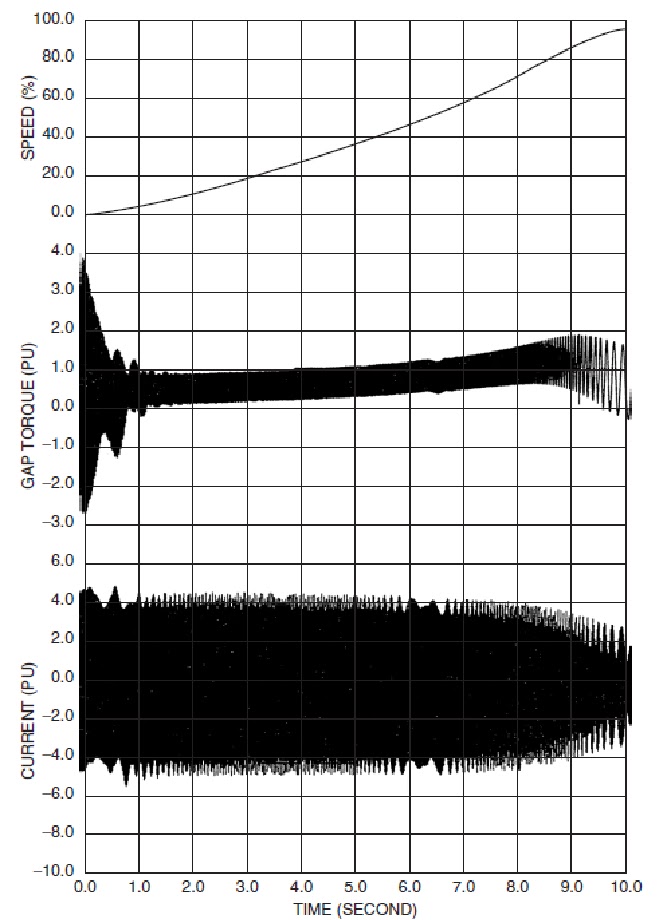
The duty on self-starting synchronous motors and condensors is severe, as there are large induction currents in the starting cage winding once the stator winding is energized (see Fig. 5.6).

FIGURE 5.6 Synchronous motor and condensor starting.

These persist as the motor comes up to speed, similar to but not identical to starting an induction motor. Similarities exist to the extent that extremely high torque impacts the rotor initially and decays rapidly to an average value, increasing with time.

Different from the induction motor is the presence of a large oscillating torque. The oscillating torque decreases in frequency as the rotor speed increases.

This oscillating frequency is caused by the saliency effect of the protruding poles on the rotor.

Meanwhile, the stator current remains constant until 80% speed is reached. The oscillating torque at decaying frequency may excite train torsional natural frequencies during acceleration, a serious train design consideration.

An anomaly occurs at half speed as a dip in torque and current due to the coincidence of line frequency torque with oscillating torque frequency. Once the rotor is close to rated speed, excitation is applied to the field coils and the rotor pulls into synchronism with the rotating electromagnetic poles.

At this point, stable steady-state operation begins.

Increasingly, variable frequency power is supplied to synchronous machinery primarily to deliver the optimum motor speed to meet load requirements, improving the process efficiency. It can also be used for soft-starting the synchronous motor or condenser.

Special design and control are employed to avert problems imposed, such as excitation of train torsional natural frequencies and extra heating from harmonics of the supply power.

PREVIOUS ARTICLES

free counters