Showing posts with label Substation. Show all posts

CLASSIFICATION OF CABLES USED IN SUBSTATION BASIC INFORMATION


No single cable characteristic should be emphasized to the serious detriment of others. A balance of cable characteristics, as well as good installation, design, and construction practices, is necessary to provide a reliable cable system.

Service conditions
a) Cables should be suitable for all environmental conditions that occur in the areas where they are installed.

b) Cable operating temperatures in substations are normally based on 40 °C ambient air or 20 °C ambient earth.

Special considerations should be given to cable installed in areas where ambient temperatures differ from these values.

c) Cables may be direct buried, installed in duct banks, conduits, and trenches below grade, or in cable trays, conduits, and wireways above ground. Cable should be suitable for operation in wet and dry locations.

High-voltage power cables are designed to supply power to substation utilization devices, other substations, or customer systems rated higher than 1000 V.

NOTE — Oil-filled and gas-insulated cables are excluded from this definition.

Low-voltage power cables are designed to supply power to utilization devices of the substation auxiliary systems rated 1000 V or less.

Control cables are applied at relatively low current levels or used for intermittent operation to change the operating status of a utilization device of the substation auxiliary system.

NOTE — leads from current and voltage transformers are considered control cables since in most cases they are used in relay protection circuits. However, when current transformer leads are in a primary voltage area exceeding 600 volts they should be protected as required by the NESC, Rule 150.

As used in this document, instrumentation cables consist of cables for Supervisory Controls and Data Acquisition (SCADA) systems or event recorders, and thermocouple and resistance temperature detector cables.

Instrumentation cables are used for transmitting variable current or voltage signals (analog) or transmitting coded information (digital).

SUBSTATION CABLE VOLTAGE RATING BASIC INFORMATION AND TUTORIALS


The selection of the cable voltage rating is based on the service conditions of 2.1, the electrical circuit frequency, phasing, and grounding configuration, and the steady-state and transient conductor voltages with respect to ground and other energized conductors.

A voltage rating has been assigned to each standard configuration of shield and insulation material and thickness in NEMA WC 3-1980, NEMA WC 5-1973, NEMA WC 7-1988, NEMA WC 8-1988, and in AEIC CS5-1987, AEIC CS6-1987, and AEIC CS7-1987.

The selected voltage rating must result in a cable insulation system that maintains the energized conductor voltage, without installation breakdown under normal operating conditions.

For high-voltage cables, it is usual practice to select an insulation system that has a voltage rating equal to or greater than the expected continuous phase-to-phase conductor voltage. The NEMA standards provide for a cable voltage rating that is only 95% of the actual continuous voltage.

For solidity grounded systems, it is usual to select the 100 Percent Insulation Level, but the 133 Percent Insulation Level is often selected where additional insulation thickness is desired. The 133 Percent Insulation Level is also applied on systems without automatic ground fault protection.

Distribution substations often utilize cable for the distribution circuits from the substation secondary switch-yard (substation getaways). The insulation system selected for this distribution cable may have a voltage rating that is a class above the minimum NEMA rating for the actual circuit voltage and ground fault protection, because it is believed that the additional insulation will result in a lower probability of insulation failure.

Research conducted by the Electric Power Research Institute has led to cable construction recommendations published in EPRI EL-6271 [B10].11 The EPRI recommendations for cable insulation systems have insulation thickness that are the same as those of the NEMA and AEIC standards.

For power and control cables applied at 600 V and below, some engineers use 1000 V-rated insulation because of past insulation failures caused by inductive voltage spikes from de-energizing electromechanical devices, e.g., relays, spring winding motors.

The improved dielectric strength of today's insulation materials prompted some utilities to return to using 600 V rated insulation for this application. Low voltage power and control cable rated 600 V and 1000 V is currently in use.

The selection of the power cable insulation system also includes consideration of cost and performance under normal and abnormal conditions. Dielectric losses, resistance to flame propagation, and gas generation when burned are the most common performance considerations.

GROUNDING GRID DESIGN IN DIFFICULT CONDITIONS BASIC INFORMATION AND TUTORIALS


In areas where the soil resistivity is rather high or the substation space is at a premium, it may not be possible to obtain a low impedance grounding system by spreading the grid electrodes over a large area, as is done in more favorable conditions.

Such a situation is typical of many GIS installations and industrial substations, occupying only a fraction of the land area normally used for conventional equipment. This often makes the control of surface gradients difficult.

Some of the solutions include

a) Connection(s) of remote ground grid(s) and adjacent grounding facilities, a combined system utilizing separate installations in buildings, underground vaults, etc. A predominant use of remote ground electrodes requires careful consideration of transferred potentials, surge arrester locations, and other critical points.

A significant voltage drop may develop between the local and remote grounding facilities, especially for high-frequency surges (lightning).

b) Use of deep-driven ground rods and drilled ground wells.

c) Various additives and soil treatments used in conjunction with ground rods and interconnecting conductors.

d) Use of wire mats. It is feasible to combine both a surface material and fabricated mats made of wire mesh to equalize the gradient field near the surface.

A typical wire mat might consist of copper-clad steel wires of No. 6 AWG, arranged in a 0.6 m × 0.6 m (24 in × 24 in) grid pattern, installed on the earth’s surface and below the surface material, and bonded to the main grounding grid at multiple locations.

e) Where feasible, controlled use of other available means to lower the overall resistance of a ground system, such as connecting static wires and neutrals to the ground. Typical is the use of metallic objects on the site that qualify for and can serve as auxiliary ground electrodes, or as ground ties to other systems. Consequences of such applications, of course, have to be carefully evaluated.

f) Wherever practical, a nearby deposit of low resistivity material of sufficient volume can be used to install an extra (satellite) grid. This satellite grid, when sufficiently connected to the main grid, will lower the overall resistance and, thus, the ground potential rise of the grounding grid.

The nearby low resistivity material may be a clay deposit or it may be a part of some large structure, such as the concrete mass of a hydroelectric dam.

BASIC ASPECT OF SUBSTATION GRID DESIGN BASIC INFORMATION AND TUTORIALS


Conceptual analysis of a grid system usually starts with inspection of the substation layout plan, showing all major equipment and structures. To establish the basic ideas and concepts, the following points may serve as guidelines for starting a typical grounding grid design:

a) A continuous conductor loop should surround the perimeter to enclose as much area as practical. This measure helps to avoid high current concentration and, hence, high gradients both in the grid area and near the projecting cable ends. Enclosing more area also reduces the resistance of the grounding grid.

b) Within the loop, conductors are typically laid in parallel lines and, where practical, along the structures or rows of equipment to provide for short ground connections.

c) A typical grid system for a substation may include 4/0 bare copper conductors buried 0.3–0.5 m (12–18 in) below grade, spaced 3–7 m (10–20 ft) apart, in a grid pattern. At cross-connections, the conductors would be securely bonded together.

Ground rods may be at the grid corners and at junction points along the perimeter. Ground rods may also be installed at major equipment, especially near surge arresters. In multilayer or high resistivity soils, it might be useful to use longer rods or rods installed at additional junction points.

d) This grid system would be extended over the entire substation switchyard and often beyond the fence line. Multiple ground leads or larger sized conductors would be used where high concentrations of current may occur, such as at a neutral-to-ground connection of generators, capacitor banks, or transformers.

e) The ratio of the sides of the grid meshes usually is from 1:1 to 1:3, unless a precise (computer-aided) analysis warrants more extreme values. Frequent cross-connections have a relatively small effect on lowering the resistance of a grid.

Their primary role is to assure adequate control of the surface potentials. The cross-connections are also useful in securing multiple paths for the fault current, minimizing the voltage drop in the grid itself, and providing a certain measure of redundancy in the case of a conductor failure.

LIGHTNING PROTECTION OF SUBSTATION DESIGN PROBLEM BASIC INFORMATION AND TUTORIALS


Substation design involves more than installing apparatus, protective devices, and equipment. The significant monetary investment and required reliable continuous operation of the facility requires detailed attention to preventing surges (transients) from entering the substation facility.

These surges can be switching surges, lightning surges on connected transmission lines, or direct strokes to the substation facility. The origin and mechanics of these surges, including lightning, are discussed in detail in Chapter 10 of The Electric Power Engineering Handbook (CRC Press, 2001).

This article focuses on the design process for providing effective shielding (that which permits lightning strokes no greater than those of critical amplitude [less design margin] to reach phase conductors [IEEE Std. 998-1996]) against direct lightning stroke in substations.

The Design Problem
The engineer who seeks to design a direct stroke shielding system for a substation or facility must contend with several elusive factors inherent in lightning phenomena, namely:

• The unpredictable, probabilistic nature of lightning
• The lack of data due to the infrequency of lightning strokes in substations
• The complexity and economics involved in analyzing a system in detail

There is no known method of providing 100% shielding short of enclosing the equipment in a solid metallic enclosure. The uncertainty, complexity, and cost of performing a detailed analysis of a shielding system has historically resulted in simple rules of thumb being utilized in the design of lower voltage facilities. Extra high voltage (EHV) facilities, with their critical and more costly equipment components, usually justify a more sophisticated study to establish the risk vs. cost benefit.

Because of the above factors, it is suggested that a four-step approach be utilized in the design of a protection system:

1. Evaluate the importance and value of the facility being protected.

2. Investigate the severity and frequency of thunderstorms in the area of the substation facility and the exposure of the substation.

3. Select an appropriate design method consistent with the above evaluation and then lay out an appropriate system of protection.

4. Evaluate the effectiveness and cost of the resulting design.

SUBSTATION SECURITY AND PROTECTION DURING EARTHQUAKE BASIC INFORMATION AND TUTORIALS


RELATIONSHIP BETWEEN EARTHQUAKE AND SUBSTATION

To secure and protect substation equipment from damage due to a seismic event, the relationship between earthquakes and substation components must first be understood. Earthquakes occur when there is a sudden rupture along a preexisting geologic fault.

Shock waves that radiate from the fracture zone amplify, and depending on the geology, these waves will arrive at the surface as a complex set of multifrequency vibratory ground motions with horizontal and vertical components.

The response of structures and buildings to this ground motion depends on their construction, ductility, dynamic properties, and design. Lightly damped structures that have one or more natural modes of oscillation within the frequency band of the ground motion excitation can experience considerable movement, which can generate forces and deflections that the structures were not designed to accommodate.

Mechanisms that absorb energy in a structure in response to its motion can help in damping these forces. If two or more structures or pieces of equipment are linked, they will interact with one another, thus producing a modified response.

If they are either not linked, or linked in such a way that the two pieces can move independently — an ideal situation — then no forces are transferred between the two components. However, recent research has shown that even a well-designed link may contribute to the response of the equipment or structure during a seismic event.

For electrical reasons, most pieces of substation power equipment are interconnected and contain porcelain. Porcelain is a relatively brittle, low-strength, and low-damping material compared with steel. Furthermore, unless instructed to do otherwise, construction personnel will install conductors with little or no slack, which gives the installation a neat and clean look.

This practice does not allow for any freedom of movement between components. When the conductor is installed with little or no slack, even small differential motions of one piece of equipment can easily impact an adjacent piece of equipment.

This is because each piece of interconnected equipment has its own frequency response to an earthquake. While the equipment at one end of a tight conductor line is vibrating at 1 Hz, for example, the other piece of equipment at the other end of the conductor is “trying” to vibrate at, say, 10 Hz.

It is easy to see that when they vibrate toward each other, the line will go slack. When they vibrate away from each other, the line will suddenly snap tight, which will impact the equipment. This is a well-documented occurrence.

Usually, the larger, more massive equipment will pull the smaller, weaker equipment over. Substation equipment with natural frequencies within the range of earthquake ground motions are especially vulnerable to this type of damage by seismic events.

RECOMMENDED FIRE PROTECTION MEASURES FOR SUBSTATION EQUIPMENT


Batteries
The hydrogen gas given off from batteries that are located in confined areas can, at certain concentrations, become an explosion hazard. Therefore, a continuously operating exhaust system should be installed when batteries are located in a room sized to contain only the battery(ies) or are located in a confined space where the buildup and retention of hydrogen gas could reach potentially explosive concentrations. 

The entrance door(s) to a battery room should have a "No Smoking" or "No Open Flame" warning sign posted on it. Lighting switches should be located outside of the room. All codes should be followed concerning the type of lighting fixtures, wiring, and installation of eye-wash stations. Precautions should also be taken to assure that the acid fumes will not be present in a concentration sufficient to cause damage to nearby relay contacts.

Surge arresters
Surge arresters should be properly sized and located to minimize the possibility of an equipment fire initiated from surges.

Direct-stroke lightning
If needed, direct-stroke lightning protection, e.g., grounded lightning masts, static wires, etc., should be installed so that all equipment and buildings are protected. Guidance in the installation of this protection can be found in ANSI/ NFPA 780-1992 [B30].

Grounding
All equipment in the substation should be properly grounded with correctly sized grounding conductors and proper terminations to dissipate fault currents. This is necessary to prevent failure of the grounding conductor or termination, which could result in more severe equipment damage and an associated fire. Guidance in grounding equipment can be found in IEEE Std 80-1986 [B45].

Fault-sensing and interrupting devices
The proper relaying or fault-sensing devices in combination with an interrupting device should protect all circuits and equipment. The combination of the devices used should operate and isolate the fault before any further and more serious problems could occur.

Metal-clad switchgear
Consideration should be given to the installation of a fixed extinguishing system for the protection of metal-clad switchgear that contains oil-filled equipment. Consideration should be given to the installation of smoke detectors on the ceiling of the switchgear room above the switchgear lineups. For guidance, see FM Data Sheet 5-19 [B41].

Oil-filled reactors
Consideration should be given to the installation of a fixed extinguishing system for the protection of oil-filled reactors. If the reactor(s) is enclosed in a sound-reducing housing, the fixed fire-extinguishing system should be installed both inside and outside the housing.

Power capacitors
Power capacitor units located outdoors, which contain a combustible dielectric fluid, should be a minimum of 10 ft (3.0 m) from any building not of fire-resistive construction. Capacitor units located indoors, which contain a flammable dielectric fluid, should be separated from adjacent areas by a 1 h fire-rated barrier.

Diesel or gasoline engines
A substation may contain diesel-, propane-, or gasoline-powered engines for fire pumps or standby electrical power. Installation of these engines should conform to ANSI/NFPA 37-1994 [B19]. Electrical apparatus on engines and generators should be fully spark-protected. For design requirements for propane fuel use, see ANSI/NFPA 58-1995 [B20].

Fuel-handling systems
Substation fuel-handling systems should conform to ANSI/NFPA 30-1993 [B18]. Buried tanks and piping should be corrosion-protected, and loading points for fuel should be located at the perimeter of the substation. Underground tanks should be located in a clearly marked area and should not be subjected to vehicle loads.

Relay and control panels
Panels should be designed and constructed to meet the recommendations for flame retardance contained in IEEE Std 420-1982 [B48].

Gas-insulated components
Consideration should be given to the control of SF6 gas and the mitigation of gas by-products that may be generated as either a direct or indirect result of fire. Precautions regarding the harmful effects of SF6 gas and SF6 gas by-products are given in IEEE Std C37.122-1993 [B43] and IEEE Std C37.122.1-1993 [B44].

High-pressure oil-filled-cable pumping plants
Consideration should be given to the installation of a fixed extinguishing system for the protection of oil-filled-cable pumping plants and storage tanks.

EQUIPMENT AND TOOL REQUIREMENTS IN GAS INSULATED SUBSTATION CONSTRUCTION BASIC INFORMATION AND TUTORIALS


Cranes or hoists having adequate lifting capacities should be available for handling material during installation. Nylon web slings provide an ideal means for lifting equipment without damaging it.

Gas is handled through commercially available gas-processing trailers that contain vacuum pumping equipment, gas storage tanks, compressors, filters, and dryers. The size of the individual gas compartments and the evacuating and storage capacity of the gas-handling equipment is especially important in large stations.

Suitable evacuating equipment and a heat source to counteract the chilling effect of the expanding gas may permit filling directly from gas cylinders or gas-handling equipment. High-voltage test equipment is required for checking the quality of the insulation after installation.

Adapters for high voltage testing may be required. These include a suitable entrance bushing for connecting the high voltage to the gas insulated conductor and a termination for closing off the end of the equipment when the entire assembly has not been completed. In many cases, it may be possible to use an entrance bushing that is a part of the installation.

When tools and alignment templates not readily available on the open market are required for installation and maintenance of the equipment, one set should be furnished, by the supplier, with the equipment when it is delivered.

The following materials should be on hand before the bus is opened:
a) Gas-processing equipment with adequate storage capacity
b) Electrolytic or electronic hygrometer or comparable equipment for measuring moisture levels
c) Insulating gas leak detector (Where double “O” rings are used, a manometer can sometimes be connected at the sensing hole to measure any increase in pressure between the “O” rings. Commercial high-viscosity, noncorrosive solutions may be used to locate larger leaks at a sensing hole, at welds, or at bolted flanges.)
d) Dry air
e) Clean plastic gloves and work uniforms
f) Lint-free cloths and manufacturer-recommended solvents
g) Temporary plastic bags or covers for sealing openings after components have been removed
h) Commercial-type vacuum cleaner with high efficiency particulate air (HEPA) filters and nonmetallic
accessories
i) Tools supplied and recommended by the manufacturer
j) Ventilating equipment
k) Handling and lifting equipment
l) Maintenance manual and erection drawings
m) Ladders and platforms as required

PARTS OF CIRCUIT SWITCHER AND ITS GENERAL CONSTRUCTION BASIC INFORMATION AND TUTORIALS


Live-tank SF6 gas puffer-type interrupters are utilized by most circuit switchers today. In the closed position, the contacts are surrounded by a flow guide and piston assembly which is ready to mechanically generate a “puff” of SF6 to cool and deionize the arc that is established prior to circuit interruption.

The moving cylinder attached to the contact assembly is driven by the main opening spring, causing the gas to be pressurized by the stationary piston. The stationary contact “follows” the moving contact as the piston assembly achieves the prepressurized gas condition.

When the contacts (which are hollow tubes) part, an arc is established and the gas flow divides into two parts and flows down the stationary and moving contact tubes. The alternating nature of the arc current waveform results in two current zeros every cycle. As long as the arc is sufficiently “hot” or conductive through the SF6 dielectric medium, the current will reestablish.

At the first current zero where the SF6 density is sufficient to stop the arc from reestablishing itself and to provide necessary dielectric strength, the arc is interrupted. This entire process from trip signal initiation to current interruption requires from 3 to 8 cycles or 50 to 133 ms in modern circuit switchers.

Figure above illustrates a typical “blade-disconnect model” circuit switcher with the interrupter and blade connected in series. For opening, the trip device, called a “shunt trip,” receives a trip signal when the relay system detects an abnormal condition within the specified range or when the operator desires a high-speed circuit opening. By discharging its operating spring, the shunt trip rotates the insulator above it at high speed, thus tripping and discharging the opening spring in the driver mechanism.

This actuates the interrupter to open the circuit. If the insulator above the shunt trip continues to rotate, by motor or manual actuation of the drive train controls, the blade opens to achieve visible isolation. The blade-hinge mechanism is actuated directly by the rotating insulator through the driver mechanism.

Continued rotation of the insulator after the blade is open will “toggle” the drive train controls to lock the blade in its open position. For closing, the reverse rotation of the insulator first releases drive train toggle and allows the blade to begin closing.

The shunt-trip units have already recharged during the opening operation. As the blade closes, the closing springs are charged in the driver. The last few degrees of closing rotation lock the blade in position and release the closing springs in the driver, thus closing the interrupter.

The opening springs are charged as the closing springs discharge. If the unit has closed into a circuit condition that provides a trip signal to the shunt trip units, the opening process may immediately proceed since all springs are charged and all controls are ready.

The closing operation may be achieved in other designs by closing the interrupter during the opening stroke of the blade. When a close operation is called for, all that is necessary is to close the blade, because the interrupter is already closed. Because of the arc established in air for this type of closing, high-speed operation of the blade is necessary to minimize damage to contacts and prevent flashovers.

Both methods of closing are proven over many years of field use. Bladeless circuit switchers operate exactly the same as blade models, except that on opening, the insulator rotation is used only for driver and interrupter actuation. Models that depend on high-speed blade operation for closing are available in bladeless nondisconnect configuration, but circuit closing must be accomplished by other means.

For models without shunt trip, opening is accomplished by rotating the insulator to the point where the driver opening spring would normally be tripped by the shunt trip’s rotation. This configuration is used where protection duty is not a function of the circuit switcher.

CIRCUIT SWITCHERS BASIC INFORMATION AND TUTORIALS


What Are Circuit Switchers?

Circuit switchers are mechanical switching devices suitable for frequent operation; not necessarily capable of high-speed reclosing; capable of making, carrying, and breaking currents under normal circuit conditions; capable of making, and carrying for a specified time, currents under specified abnormal conditions; and capable of breaking currents under certain other specified abnormal circuit conditions.

They may include an integral isolating device. Circuit switchers available today use SF6 as an interrupting medium and may be equipped with a trip device connected to a relay to open the circuit switcher automatically under specified abnormal conditions, such as overcurrent or faults.

A circuit switcher, like a circuit breaker, must carry normal load currents within a specified temperature range to prevent damage to key components such as contacts, linkage, terminals, and isolating device parts.

Principal designating parameters of a circuit switcher are maximum operating voltage, BIL, rated load current, interrupting current, whether an isolator is required, whether a trip device is required, and whether manual or motorized operation is required.

A circuit switcher essentially combines the functions of a circuit breaker (without reclosing capability) and a disconnecting switch (by providing visible isolation, but not necessarily meeting the safety requirements of all users).

A circuit switcher provides a cost-effective alternative means of transformer protection and switching, line and loop switching, capacitor or reactor switching, and load management, with protection in most instances.

Evolution of the circuit switcher concept provides a more in-depth understanding of its application versatility and its limitations.

History of Circuit-Switcher Development
After World War II, the drive to electrify the remaining rural and sparsely populated areas of the United States was renewed. Providing fully rated circuit breakers for switching loaded circuits was frequently beyond budget limitations. This created a need for new transmission and subtransmission voltage circuit-switching devices.

One such device could be described as a load interrupter. It appeared in a wide variety of forms. Most were attachments to disconnect switches.

Initially, most of these devices used low-volume oil as an interrupting medium. Ablative gas generating devices and later vacuum displaced oil. With rare exceptions, these devices had deficiencies. In the mid-1950s, SF6 was first employed as an interrupting medium. The application was an interrupter attachment for disconnect switches.

Whereas ablative devices and vacuum bottles are limited to approximately 30-kV recovery voltage per gap, this single-gap SF6 device was readily applied on 138-kV systems for up to 600 A load switching.

Most of these vacuum, ablative, and SF6 devices were shunted into the circuit during the disconnect switch opening process. As the 1960s approached, the circuit switcher was born. It appeared as an in line device. While the first version employed a number of ablative devices in series, it soon evolved into the use of SF6 as a medium.

Because of the unfavorable experience with the earlier devices, the general acceptance of the circuit switcher took much effort and considerable time. A typical installation is shown below.


Applications for circuit switchers have been primarily for transformer protection. The circuit switcher provides load-switching capability and mainly protection for faults that originate on the secondary side of the substation transformer.

The zone of protection for circuit switchers in this location is typically from the current transformers inside the transformer on the high-voltage bushings to the secondary feeder breakers. There is generally shorter strike distance on the secondary bus and more exposure to flashover from wildlife and other causes.

Therefore, circuit switchers are specifically tested to interrupt the higher transient recovery voltages (TRVs) associated with faults initiated on the secondary of the transformer and cleared by the high-side protective device. For application where the available high-side short-circuit current exceeds the device’s capability, blocking relays can be used. However, in most applications this is not necessary.

AUTOMATED SWITCHES USED IN POWER SYSTEM BASIC INFORMATION AND TUTORIALS


A key part of an automated feeder switching system is the automated switch. The term “automated” in this context means the switch is designed for use on an automated or SCADA system.

In order to be automated, existing switches may be retrofitted with motor operators, current and voltage sensors, RTUs and communication devices to allow the remote operation necessary to realize the benefits available with automated feeder switching systems.

However, switches designed for occasional, manual operation may not be entirely suitable for operation on an automated distribution circuit feeder. Manual switches are typically not designed to be operated the hundreds of times required by a fully automated system over the life of a typical switch.

Nor are they ordinarily designed for duty cycle fault-closing to allow the system operator to inadvertently close into a fault from the SCADA master station—and still leave the switch in an operable condition.

More recently, switches designed specifically for automation have appeared in the market like the one below.


Such switches incorporate design features that make them particularly applicable for use in an automated feeder switching system:

1. Duty-cycle fault-closing allows the switch to be closed into a typical fault several times before experiencing damage severe enough to render the switch inoperable.

2. Integrated voltage and current sensors provide the ability to monitor voltages, currents, and loads that are in turn used as inputs to algorithms to effect automated switching for fault isolation and restoration and for shifting loads for circuit optimization.

3. Integrated operating mechanisms enable the switches to be operated remotely via computer commands. Integration with the switch ensures optimum operation without the need for cumbersome ground-to-switch linkages.

4. Integrated load interrupters should be designed to allow operation under any weather conditions since it will not be possible to visibly inspect the switch for ice or other problems prior to operation.

5. Integrated control power sources eliminate the need to rely on locally available control power sources—or to install such power sources.

6. Integrated visible air-gap isolation provides the visible air gap when needed for certain types of line work.

In addition, an associated control package should include switch-operating controls, a local/remote switch, backup power for dead-line SCADA operation, a remote-terminal unit, and data communication devices. The entire package should be assembled and tested for proper operation by a single supplier to eliminate the need for the utility to perform the integration.

The control box should be separately located from the switch to allow access by technicians who are not qualified in high-voltage operations. In underground switchgear applications, the control should be isolated from the high-voltage compartments of the switchgear.

ELECTRIC AND MAGNETIC FIELD OF A POWER SUBSTATION BASIC INFORMATION ANF TUTORIALS


Electric substations produce electric and magnetic fields. In a substation, the strongest fields around the perimeter fence come from the transmission and distribution lines entering and leaving the substation.

The strength of fields from equipment inside the fence decreases rapidly with distance, reaching very low levels at relatively short distances beyond substation fences. In response to the public concerns with respect to EMF levels, whether perceived or real, and to governmental regulations, the substation designer may consider design measures to lower EMF levels or public exposure to fields while maintaining safe and reliable electric service.

Electric and Magnetic Field Sources in a Substation
Typical sources of electric and magnetic fields in substations include the following:
1. Transmission and distribution lines entering and exiting the substation
2. Buswork
3. Transformers
4. Air core reactors
5. Switchgear and cabling
6. Line traps
7. Circuit breakers
8. Ground grid
9. Capacitors
10. Battery chargers
11. Computers

Electric Fields
Electric fields are present whenever voltage exists on a conductor. Electric fields are not dependent on the current. The magnitude of the electric field is a function of the operating voltage and decreases with the square of the distance from the source. The strength of an electric field is measured in volts per meter.

The most common unit for this application is kilovolts per meter. The electric field can be easily shielded (the strength can be reduced) by any conducting surface such as trees, fences, walls, buildings, and most structures. In substations, the electric field is extremely variable due to the screening effect provided by the presence of the grounded steel structures used for electric bus and equipment support.

Although the level of the electric fields could reach magnitudes of approximately 13 kV/m in the immediate vicinity of high-voltage apparatus, such as near 500-kV circuit breakers, the level of the electric field decreases significantly toward the fence line. At the fence line, which is at least 6.4 m (21 ft) from the nearest live 500-kV conductor (see the NESC), the level of the electric field approaches zero kV/m. If the incoming or outgoing lines are underground, the level of the electric field at the point of crossing the fence is negligible.

Magnetic Fields
Magnetic fields are present whenever current flows in a conductor, and are not voltage dependent. The level of these fields also decreases with distance from the source but these fields are not easily shielded. Unlike electric fields, conducting materials such as the earth, or most metals, have little shielding effect on magnetic fields. Magnetic fields are measured in Webers per square meter (Tesla) or Maxwells per square centimeter (Gauss). One Gauss = 10^–4 Tesla. The most common unit for this application is milliGauss (10^–3 Gauss).

Various factors affect the levels of the fields, including the following:

1. Current magnitude
2. Phase spacing
3. Bus height
4. Phase configurations
5. Distance from the source
6. Phase unbalance (magnitude and angle)

Magnetic fields decrease with increasing distance (r) from the source. The rate is an inverse function and is dependent on the type of source. For point sources such as motors and reactors, the function is 1/ r^2; and for single-phase sources such as neutral or ground conductors the function is 1/r.

Besides distance, conductor spacing and phase balance have the largest effect on the magnetic field level because they control the rate at which the field changes. Magnetic fields can sometimes be shielded by specially engineered enclosures. The application of these shielding techniques in a power system environment is minimal because of the substantial costs involved and the difficulty of obtaining practical designs.

GAS INSULATED SUBSTATION CONSTRUCTION AND SERVICE LIFE BASIC INFORMATION


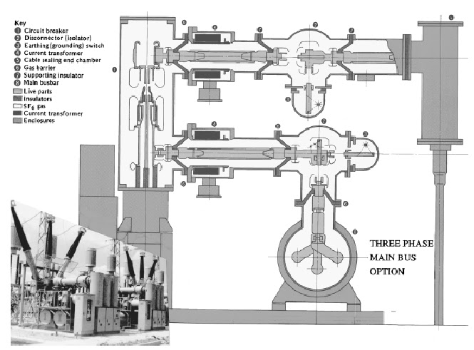
GIS is assembled of standard equipment modules (circuit breaker, current transformers, voltage transformers, disconnect and ground switches, interconnecting bus, surge arresters, and connections to the rest of the electric power system) to match the electrical one-line diagram of the substation.

A cross section view of a 242-kV GIS shows the construction and typical dimensions (Figure 2.1). The modules are joined using bolted flanges with an “O” ring seal system for the enclosure and a sliding plug-in contact for the conductor.


Internal parts of the GIS are supported by cast epoxy insulators. These support
insulators provide a gas barrier between parts of the GIS, or are cast with holes in the epoxy to allow gas
to pass from one side to the other.

Up to about 170 kV system voltage, all three phases are often in one enclosure (Figure 2.2). Above 170 kV, the size of the enclosure for “three-phase enclosure,” GIS becomes too large to be practical. So a “single-phase enclosure” design (Figure 2.1) is used.

There are no established performance differences between three-phase enclosure and single-phase enclosure GIS. Some manufacturers use the single phase enclosure type for all voltage levels.

Enclosures today are mostly cast or welded aluminum, but steel is also used. Steel enclosures are painted inside and outside to prevent rusting. Aluminum enclosures do not need to be painted, but may be painted for ease of cleaning and a better appearance. The pressure vessel requirements for GIS enclosures are set by GIS standards (IEEE Std. C37.122-1993; IEC, 1990), with the actual design, manufacture, and test following an established pressure vessel standard of the country of manufacture.

Because of the moderate pressures involved, and the classification of GIS as electrical equipment, third-party inspection and code stamping of the GIS enclosures are not required.

Conductors today are mostly aluminum. Copper is sometimes used. It is usual to silver plate surfaces that transfer current. Bolted joints and sliding electrical contacts are used to join conductor sections. There are many designs for the sliding contact element. In general, sliding contacts have many individually sprung copper contact fingers working in parallel. Usually the contact fingers are silver plated.

A contact lubricant is used to ensure that the sliding contact surfaces do not generate particles or wear out over time. The sliding conductor contacts make assembly of the modules easy and also allow for conductor movement to accommodate the differential thermal expansion of the conductor relative to the enclosure.

Sliding contact assemblies are also used in circuit breakers and switches to transfer current from the moving contact to the stationary contacts. Support insulators are made of a highly filled epoxy resin cast very carefully to prevent formation of voids and/or cracks during curing.

Each GIS manufacturer’s material formulation and insulator shape has been developed to optimize the support insulator in terms of electric field distribution, mechanical strength, resistance to surface electric discharges, and convenience of manufacture and assembly. Post, disc, and cone type support insulators are used.

Quality assurance programs for support insulators include a high voltage power frequency withstand test with sensitive partial discharge monitoring. Experience has shown that the electric field stress inside the cast epoxy insulator should be below a certain level to avoid aging of the solid dielectric material.

The electrical stress limit for the cast epoxy support insulator is not a severe design constraint because the dimensions of the GIS are mainly set by the lightning impulse withstand level and the need for the conductor to have a fairly large diameter to carry to load current of several thousand amperes. The result is space between the conductor and enclosure for support insulators having low electrical stress.

Service life of GIS using the construction described above has been shown by experience to be more than 30 years. The condition of GIS examined after many years in service does not indicate any approaching limit in service life.

Experience also shows no need for periodic internal inspection or maintenance. Inside the enclosure is a dry, inert gas that is itself not subject to aging. There is no exposure of any of the internal materials to sunlight. Even the “O” ring seals are found to be in excellent condition because there is almost always a “double seal” system. The lack of aging has been found for GIS, whether installed indoors or outdoors.

ECONOMICS OF GAS INSULATED SUBSTATION (GIS) BASIC INFORMATION


A gas-insulated substation (GIS) uses a superior dielectric gas, SF6, at moderate pressure for phase-to phase and phase-to-ground insulation. The high voltage conductors, circuit breaker interrupters, switches, current transformers, and voltage transformers are in SF6 gas inside grounded metal enclosures.

The atmospheric air insulation used in a conventional, air-insulated substation (AIS) requires meters of air insulation to do what SF6 can do in centimeters. GIS can therefore be smaller than AIS by up to a factor of 10.

A GIS is mostly used where space is expensive or not available. In a GIS the active parts are protected from the deterioration from exposure to atmospheric air, moisture, contamination, etc. As a result, GIS is more reliable and requires less maintenance than AIS.

The equipment cost of GIS is naturally higher than that of AIS due to the grounded metal enclosure, the provision of an LCC, and the high degree of factory assembly. A GIS is less expensive to install than an AIS.

The site development costs for a GIS will be much lower than for an AIS because of the much smaller area required for the GIS. The site development advantage of GIS increases as the system voltage increases because high voltage AIS take very large areas because of the long insulating distances in atmospheric air.

Cost comparisons in the early days of GIS projected that, on a total installed cost basis, GIS costs would equal AIS costs at 345 kV. For higher voltages, GIS was expected to cost less than AIS. However, the cost of AIS has been reduced significantly by technical and manufacturing advances (especially for circuit breakers) over the last 30 years, but GIS equipment has not shown any cost reduction until very recently.

Therefore, although GIS has been a well-established technology for a long time, with a proven high reliability and almost no need for maintenance, it is presently perceived as costing too much and is only applicable in special cases where space is the most important factor.

Currently, GIS costs are being reduced by integrating functions as described in the arrangement section above. As digital control systems become common in substations, the costly electromagnetic CTs and VTs of a GIS will be replaced by less-expensive sensors such as optical VTs and Rogowski coil CTs.

These less-expensive sensors are also much smaller, reducing the size of the GIS and allowing more bays of GIS to be shipped fully assembled. Installation and site development costs are correspondingly lower. The GIS space advantage over AIS increases. GIS can now be considered for any new substation or the expansion of an existing substation without enlarging the area for the substation.

GAS INSULATED SUBSTATION BASIC INFORMATION AND TUTORIALS


What Are Gas Insulated Substations?

High-voltage gas-insulated substations have been in service since the early 1960s. Operation of 800-kV equipment has proved successful since the end of 1979. Prototype testing of 1100 through 1600-kV substation equipment proved the feasibility of this equipment at the next generation of voltage levels.

The basic principle of gas-insulated equipment is that the high-voltage current-carrying parts are within a metal enclosure and are held in a concentric configuration by cast epoxy spacer insulators. The space between the conductor and the enclosure is filled with sulfur hexafluoride gas under moderate pressure.

Medium-voltage to 170-kV equipment is available in three phases in one enclosure; for higher voltages, it is generally in a single-phase enclosure arrangement. The equipment can be installed indoors or outdoors, and it can be designed for any bus scheme.

Depending on the voltage level, bus scheme, and whether connecting lines are installed underground or overhead, the land area required for gas-insulated equipment is 10% for 800 kV to 20% for 145 kV of the space required for comparable air-insulated equipment.

Because of its smaller size and enclosed current-carrying parts, this equipment is excellently suited for installation where real estate is at a premium, where the environmental constraints dictate a minimum of visual exposure, and where the continuity of service may be threatened by airborne contamination.

The dielectric medium is the sulfur hexafluoride (SF6) gas, which became commercially available in 1947. SF6 has been used as an insulating medium in electronic devices, power apparatus, and HVDC converter stations. Its excellent properties make it ideally suited both as an insulating and as an arc-quenching agent. SF6 gas is colorless, odorless, chemically inert, nontoxic, nonflammable, and noncorrosive.

Its dielectric strength is greatly superior to that of air, and it is close to 100 times as effective as air in quenching an electric arc. Pure SF6 is heavier than air, which causes it to settle in low areas, thus diluting oxygen in air. It is therefore necessary to learn proper safety rules before entering any area where pockets of SF6 could accumulate.

Although the gas is self-restoring, during its exposure to an electric arc it will yield decomposition by products. In the presence of moisture, which is especially the case in failed and ruptured equipment, these by-products will hydrolyze, and all resulting reaction products must be considered hazardous.

The level of gas pressure at which the equipment will operate to meet specified ratings is a function of the relationship between diameters of the conductor and the enclosure (the size of the gap), and the temperature at which the equipment will operate. At the higher pressures, the gas would liquefy at higher temperatures.

At lower pressures, dielectric strength and arc-quenching qualities of the gas would be reduced. Therefore, the gas-insulated equipment operating pressure is usually between 0.35 and 0.52 MPa (50 and 75 lb/in2, gage).

Environmental effects of SF6 that might be released to the atmosphere from GIS have been thoroughly studied. SF6 does not affect the earth’s ozone layer, but it is a strong greenhouse gas. Relative to CO2, it has a global warming potential of 23,400 due to its infrared absorption and emission characteristics and very long life in the atmosphere (half-life is projected to be 3200 years).

Fortunately, the concentration of SF6 in the atmosphere is very low, and with proper handling, leak checking, and recycling, the contribution of SF6 to anthropogenic global warming due to its use in electrical equipment can be kept below 0.1%.

SURGE PROTECTION OF SUBSTATION BASIC INFORMATION AND TUTORIALS


What Are The Means To protect The Substation From Surges?

A substation should be designed to include safeguards against the hazards of abnormally high voltage surges that can appear across the insulation of electrical equipment in the station. The most severe overvoltages are caused by lightning strokes and by switching surges.

The main methods to prevent these overvoltages from causing insulation failures include:
1. Use of surge arresters
2. Equipment neutral grounding
3. Proper selection of equipment impulse insulation level
4. Proper selection and coordination of equipment basic insulation levels
5. Careful study of switching-surge levels that can appear in the substation

The main device used to prevent dangerous overvoltages, flashovers, and serious damage to equipment is the surge arrester. The surge arrester conducts high surge currents, such as can be caused by a lightning stroke, harmlessly to ground and thus prevents excessive overvoltages from appearing across equipment insulation.

The important consideration in applying surge arresters and in selecting equipment insulation levels depends greatly on the method of grounding used. Systems are considered to be effectively grounded when the coefficient of grounding does not exceed 80%. Similarly, systems are noneffectively grounded or ungrounded when the coefficient of grounding exceeds 80%.

A value not exceeding 80% is obtained approximately when, for all system conditions, the ratio of zero sequence reactance to positive sequence reactance (X0/X1) is positive and less than 3 and the ratio of zero sequence resistance to positive sequence reactance (R0/X1) is positive and less than 1.

What this says in effect is that if neutrals are grounded solidly everywhere and if a ground occurs on one of the conductors, then the voltage that can appear on the healthy phases cannot exceed 80% of normal phase-to-phase voltage.

Thus, the coefficient of grounding is defined as the ratio of maximum sustained line-to-ground voltage during faults to the maximum operating line-to-line voltage. On many HV and EHV systems, the coefficient of grounding may be as low as 70%.

Surge-arrester ratings are normally selected on the basis of the coefficient of grounding; thus, for effectively grounded systems, the 80% arrester is selected when using the conventional gap-type arrester. When using the gapless metal oxide arrester, a lower-value arrester may be selected based on the maximum continuous operating voltage (MCOV) equal to the maximum normal line-to-neutral voltage.

For example, a 115-kV system (maximum operating voltage equals 121 kV) can use a 97-kV conventional arrester, that is, 80% of 121 kV, when operating on a solidly grounded system, and can use a gapless-type metal oxide arrester rated 70 kV. It should be noted that other factors, such as resonant conditions and system switching, could increase the value of the coefficient of grounding and thus should be studied in each individual system.

The impulse insulation level of a piece of equipment is a measure of its ability to withstand impulse voltage. It is the crest value, in kilovolts, of the wave of impulse voltage that the equipment must withstand. However, at EHV, the switching-surge insulation level may be lower than the corresponding impulse level, and thus the switching-surge level becomes the dominant factor in establishing insulation levels.

Basically, the coordination of insulation in a substation means the use of no higher-rated arrester than required to withstand the 60-Hz voltage and the choice of equipment insulation levels that can be protected by the arrester.

Careful study of switching-surge levels that can occur at the substation as determined, for example, by transient network analyzer studies also can be used to determine and coordinate proper impulse insulation and switching-surge strength required in a substation electrical equipment.

SUBSTATION ELECTRICAL BUS AND PARTS CLEARANCES REQUIREMENTS BASIC INFORMATION AND TUTORIALS


In 1972, the Substations Committee of the IEEE published Trans. Paper T72 131-6, which established recommendations for minimum line-to-ground electrical clearances for EHV substations based on switching-surge requirements. The recommendations are based on a study of actual test data of the switching-surge strength characteristics of air gaps with various electrode configurations as reported by many investigators.

The results are shown in Table 17-5 and include minimum line to- ground clearances for EHV system voltage ratings of 345, 500, and 765 kV.

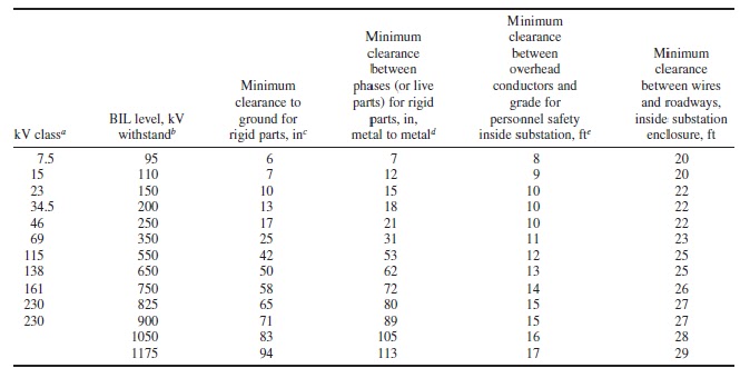
The clearances given in Table 17-4 are considered adequate for both line-to-ground and phase-to-phase values for the voltage classes up through 230 kV nominal system voltage where air-gap distances are dictated by impulse (BIL) withstand characteristics.

The National Electric Safety Code, IEEE Standard C2-2002, also includes clearance requirements to the substation fence.

The Substations Committee of the IEEE has an ongoing effort to review phase-to-phase air clearances and is currently balloting IEEE Standard P1427, Guide for Recommended Electrical Clearances and Insulation Levels in Air Insulated Power Substations.

Considerable information has been published by CIGRE relative to establishing phase-to-phase air clearances in EHV substations as required by switching surges. The CIGRE method is based on nearly simultaneous and equal opposite-polarity surge overvoltages in adjacent phases.

The phase to-ground surge overvoltage is multiplied by a factor of up to 1.8 (the theoretical maximum phase to-phase voltage would be twice the phase-to-ground surge overvoltage). The estimated value of phase-to-phase overvoltage is then compared with obtained clearances. Refer to an article in CIGRE, Electra, no. 29, 1973, “Phase-to-Ground and Phase-to-Phase Air Clearances in Substations,” by L. Paris and A. Taschini.

Suggested values of phase-to-phase clearances for EHV substations based on the CIGRE method are shown in Table 17-6. The table was formulated by choosing various phase-to-ground transient voltage values such as are used in Table 17-5.

These values of phase-to-ground overvoltage were multiplied by a factor of 1.8 to arrive at a value of estimated phase-to-phase transient overvoltages.

An equivalent phase-to-phase critical flashover value of voltage is next assumed by multiplying the switching-surge phase-to-phase voltage by 1.21. Finally, this value is compared with data in the CIGRE article prepared by Paris and Taschini to arrive at air-clearance values based on switchingsurge impulse voltages.

EHV substation bus phase spacing is normally based on the clearance required for switching-surge impulse values plus an allowance for energized equipment projections and corona rings. This total distance may be further increased to facilitate substation maintenance.

TABLE 17-4 Minimum Electrical Clearances for Standard BIL Outdoor Alternating Current

TABLE 17-5 Minimum Electrical Clearances for EHV Substations Based on Switching Surge and Lightning Impulse Requirements (Line to ground)

Notes:
1. Minimum clearances should satisfy either maximum switching-surge or BIL duty requirement, whichever dictates the larger dimension.
2. For installations at altitudes in excess of 3300 ft elevation, it is suggested that correction factors, as provided in IEEE C37.30-1992, be applied to withstand voltages as given above.

SS: switching surge
CFO: critical flashover
1 in # 25.4 mm.

TABLE 17-6 Suggested Electrical Clearances for EHV Substations Based on Switching Surge Requirements and Including U.S. Utility Practice (Phase to phase)
Note: 1 in # 25.4 mm; 1 ft # 0.3048 m.
∗The values of L-L switching-surge clearances are based on the use of SS L-G crest voltages multiplied by 1.8. This value of L-L SS voltage is then multiplied by 1.21 to indicate an SS CFO value of voltage used to determine the clearances.

For a description of method used, refer to CIGRE report by L. Paris and A. Taschini, Phase-to-Ground and Phase-to-Phase Air Clearances in Substations, CIGRE, Electra, no. 29, 1973, pp. 29–44. L-G: line to-ground; L-L: line-to-line; SS: switching surge; CFO: critical flashover.


SUBSTATION SECURITY BASIC INFORMATION AND TUTORIALS


The preparation of a security plan shall require answering the following:
a) Why is the plan needed?
b) Who will administer the plan?
c) What security measures are required by the individual facility?

These questions need to be addressed before a comprehensive and cost-effective security plan can be created.

Objective of the security plan
For any plan to be successful, it must have a clearly stated objective. Using historical operating data, demographics information, and industry experience, each company can determine the level and type of security required.

Defining the objective will help focus attention on those security methods most appropriate to the company’s needs. The objective should state the present and primary concerns, such as vandalism and theft in existing stations, or theft and injury during substation construction.

Responsibility for security
Identification of the person or persons responsible for security implementation and administration is critical to the effectiveness of the plan. Therefore, defined levels of responsibility and specific tasks are required for each level.

Each company should have someone in charge of facilities security. This individual should be responsible for assuring that a security plan is developed, implemented, regularly reviewed, and updated.

Regular inspection of facilities to assure that security measures are in effect should be part of the security plan, along with employee training and methods that enable employees to report irregularities or breaches of security.

Basic security requirements
All existing and new substations have a basic minimum level of security required. This includes fences with locked gates, control buildings with locked doors, a special type of grounding system if copper theft is prevalent, and minimum clearance distances between perimeter fences and energized equipment.

Basic security requirements should list these measures as required in all cases, regardless of location or age of the station. In addition, some types of security breach may require special or immediate action by operations staff.

For example, damage to the ground system of an energized station should be treated with care in case of the unlikely event of a dangerous touch potential. These types of security breaches should be noted in the security plan.

At construction and material storage sites, or vacant land, minimum security levels may either not exist, or may be inadequately described. Therefore, it is important to define the security measures required by type of facility or site, especially if the measures required are different from other basic measures normally required.

For instance, vacant land should be inspected on a regular basis for evidence of use for illicit activities, unauthorized dumping, and existence of holes that could cause injury due to falls. Security methods at active construction sites can include moving all construction equipment inside of fenced areas at night and checkin/ check-out of personnel through a security gate.

Additional security measures
Additional security measures, over and above the basic requirements, may be determined to be necessary based on the security survey results. The increased security measures required should be based on restricted access or high-risk areas. The types of security used in these instances could include motion detectors, perimeter/area detection systems, security cameras, jersey barriers, and posted guards.

MOBILE SUBSTATION ITEMS THAT NEEDS TO BE GROUNDED BASIC INFORMATION AND TUTORIALS


What are the substation items that needs grounding?

Fence
The fences may be either connected to the mobile substation grid or isolated. A dangerous voltage may exist if an isolated conducting (metallic) fence and the trailer can be bridged by a person standing between them. 

Connecting the fence and trailer together will lower the voltage between them, even if they may not be touched at the same time. If an ungrounded conducting temporary fence is installed adjacent to a grounded substation fence, an isolation section may be necessary to prevent a transfer voltage on the temporary fence.

Gate
A conducting gate should be bonded to a conducting fence. If the gate swings outward, a loop conductor should be
installed to control the touch voltages when opening the gate. If the gate opens inward, no special grounding may be
needed unless the fence is isolated from the mobile substation’s ground grid.

Trailer frame
The trailer frame and/or trailer ground bus should be connected to the grid with a conductor of a size adequate to carry the available fault current. If the trailer has no ground bus for the equipment connections, all equipment and the trailer should be connected to the mobile substation ground grid using separate conductors of proper size for each piece of equipment.

Multiple trailers (e.g., a switch and fuse trailer used with a mobile transformer trailer) should be connected via the grid or a direct cable tie to prevent voltages between them. Caution should be taken while any maintenance is performed on the trailer (e.g., changing or removing tires and adjusting jacks) while the unit is in service. Movable (e.g., slide-out switch bases, etc.) or removable conducting parts (e.g., steps, dollies, etc.) should be connected to the trailer ground bus or the ground grid, or both, to eliminate voltages between them.

Cable shield grounding
Cable shields should be grounded. If the cable shield is to be grounded at both ends, the shield must be sized to conduct fault current or have a separate parallel conductor to prevent excessive current in the shield. Refer to IEEE Std 525-1992 for further guidance.

Operator platforms or plates
In the absence of a properly designed ground grid, operator platforms or plates should be installed and connected to the grid at all switch handles that are accessible from the ground. In the case of a properly designed ground grid, operator platforms and plates may be installed as a supplement to the ground grid and connected to the grid. If the trailer jacks are to be adjusted while the mobile substation is in service, a platform or plates connected to the grid should be installed at the jack handle.

Neutral grounding
Neutral conductors of adequate fault-current capacity should be installed from the mobile transformer to the grid. Feeder neutrals should be connected to the provided attachment point (neutral bushing) or directly to the grid. If possible, transmission line shield wires should be connected to the grid.

Due to the higher resistance of a separate mobile grid not connected to the main substation grid, a high percentage of the fault current will flow on the neutral and transmission line shield wires. In some cases, the current limits of these wires may be exceeded by return currents.

When the mobile substation is located outside the substation fence, the grids should be connected together, if practical, to lower the ground potential rise. Installation of two or more ground cables is desirable to reduce the inductive reactance between the two ground mats and to lower the transient overvoltages.

Temporary equipment
Any temporary equipment connected to the trailer or equipment on the trailer should be grounded to the grid or trailer ground bus.

POWER SUBSTATION CONSTRUCTION CIVIL WORKS BASIC INFORMATION


High-voltage power electronic substations are special because of the valve rooms and buildings required for converters and controls, respectively. Insulation clearance requirements can lead to very large valve rooms (halls).

The valves are connected to the yard through wall bushings. Converter transformers are often placed adjacent to the valve building, with the valve-side bushings penetrating through the walls in order to save space.

The valves require controlled air temperature, humidity, and cleanness inside the valve room. Although the major part of the valve losses is handled by the valve cooling system, a fraction of the same is dissipated into the valve room and adds to its air-conditioning or ventilation load.

The periodic fast switching of electronic converter and controller valves causes a wide spectrum of harmonic currents and electromagnetic fields, as well as significant audible noise. Therefore, valve rooms are usually shielded electrically with wire mesh in walls and windows.

Electric interference with radio, TV, and communication systems can usually be controlled with power line carrier filters and harmonic filters. Sources of audible noise in a converter station include the transformers, capacitors, reactors, and coolers.

To comply with the contractually specified audible noise limits within the building (e.g., in the control room) and outdoors (in the yard, at the substation fence), low-noise equipment, noise-damping walls, barriers, and special arrangement of equipment in the yard may be necessary. The theory of audible
noise propagation is well understood, and analytical tools for audible noise design are available.

Specified noise limits can thus be met, but doing so may have an impact on total station layout and cost. Of course, national and local building codes also apply.

In addition to the actual valve room and control building, power electronic substations typically include rooms for coolant pumps and water treatment, for auxiliary power distribution systems, air conditioning systems, battery rooms, and communication rooms.

Extreme electric power flow densities in the valves create a certain risk of fire. Valve fires with more or less severe consequences have occurred in the past.

Improved designs as well as the exclusive use of flame-retardant materials in the valve, coordinated with special fire detection and protection devices, reduce this risk to a minimum. The converter transformers have fire walls in between and dedicated sprinkler systems around them as effective fire fighting equipment.

Many high-voltage power electronic stations have spare transformers to minimize interruption times following a transformer failure. This leads to specific arrangements and bus configurations or extended concrete foundations and rail systems in some HVDC converter stations.

Some HVDC schemes use outdoor valves with individual housings. They avoid the cost of large valve buildings at the expense of a more complicated valve maintenance. TCSC stations also have similar valve housings on insulated platforms together with the capacitor banks and other equipment.

PREVIOUS ARTICLES

free counters